4
8.0 FIXING THE APPLAINCE - CONTINUED
GB IE
' 2013 Focal Point Fires plc.
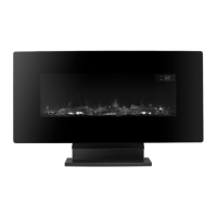
For optimum viewing, mark the top four screws fixing positions on wall in accordance with
the recommend fixing dimensions- see figure 2.
NOTE: Ensure that the bracket is level by using a Spirit level whilst marking out the hole posi-
tions.
Drill holes with a 5mm drill bit. Fix the wall bracket using the plugs and screws provided.
Attach the lower fixing bracket to the base of the fire using the two small black screws sup-
plied; ensure the bracket is fitted so that it is level with the back.
Carefully lift the heater up ensuring that the top rear ledge of heater engages with the wall
bracket (see figure 2 in circle) and is sitting centrally. This process should be carried out by
two people to avoid injury or damage to property or the appliance.
Gently bring the heater down against the wall.
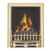
Mark the lower fixing bracket two fixing hole positions on the wall (see figure 3), remove the
heater.
Drill the wall and insert the wall plugs.
Refit the heater to the wall and fasten the bottom fixing bracket to the wall using the screws
provided to permanently fix the heater in place.
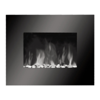
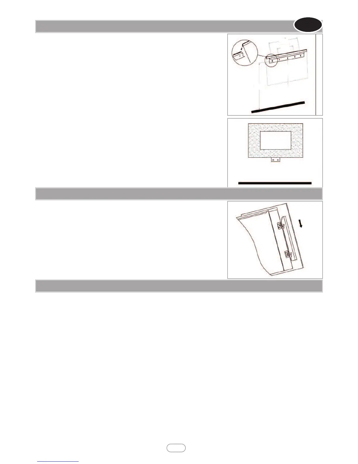
Unpack the pebbles from the bag and place them along the light unit in the desired position.
Place the front surround over the front of the fire aligning the slots in the brackets at each
side of the front panel with the lugs on the sides of the fire. See figure 4.
Again two people will be required for this operation.
READ ALL INSTRUCTIONS BEFORE USE!
Check that the heater outlet grille, mounted at the top of the appliance, is not covered or obstructed in any way, and ensure the power to the
fire is switched on.
Manual Operation
• The switches located at the top right hand side of the fire .The standby switch must be first switch on.
• Press once the O/I button to turn on the appliance and fire effect. A red indicator light will appear to indicate that the function is ON. Press
the O/I button for 3 seconds this will operate the dimmer mode. There are 5 levels flame brightness available.
• Press once the POWER button for the low heat settings 900W, a red indicator light will appear to indicate the function; press twice for high
heat settings 1800W, a red indicator light will appear to indicate the function; press third to switch off the heat setting.
• Press BACKLIGHT button to operate backlight function. 7 colors backlights available.
Remote Operation
• The standby switch located at the top right hand side of the fire must be first switch on..
• It takes some time for the receiver to respond to the transmitter. Do not PRESS the buttons more than once within two seconds for cor-
rect operation.
• Press once the button ON/OFF on the remote control this turns ON/OFF the appliance and fire effect.
• Press once the 900W/1800W button for the low heat settings 900W, a red indicator light on manual operation panel will appear to indicate
the function; press twice for the high heat settings 1800W, a red indicator light on manual operation panel will appear to indicate the function;
press third to switch off the heat setting.
• Press BACKLIGHT button to operate backlight function. 7 colors backlights available.
• Press the DIMMER button for operate the dimmer mode. There are 5 levels flame brightness available.
10.0 OPERATING THE APPLIANCE
Figure 4
Figure 2
460
160
1045
Figure 3
9.0 FITTING THE FRAME AND FUEL BED