2: Fully recessed - If you are putting the fire against a wall with a recess of 66mm
or more, you will be able to remove the spacer that is fitted to the fire, so that your
fire can sit further back on the hearth. To secure the fire to the wall you will be able
to use double sided neoprene. See method 2 - Neoprene and see section 7.0
Removing the appliance spacer frames.
2
mm
Method 2 - Neoprene
Neoprene - To use the double sided neoprene strip, you will need to cut the length
into two equal pieces. Install one either side of the rear of the trim.
4
© 2015 Focal Point Fires plc.
6.0 INSTALLING THE APPLIANCE
1: Flat wall - If you are putting the fire against a wall with no recess, you will use
the spacer that is fitted to the fire. You will be able to use either the sticky double
sided neoprene strips, or, secure the fire to the wall using the key hole slots on the
rear of the spacer frame with screws provided.
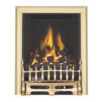
Method 1 - Screw fixings
Using suitable fixings for your wall or surround, mark the centre of your opening
and measure 213mm to the left and then again to the right. From there measure
from the floor 526mm up the wall. This will be the centre of the screws. See figure
1. From the floor measure up 9mm and 77mm either side of the centre line for the
bottom two fixings. If you are using the wall plugs supplied a hole of 8mm diameter
to a depth of 40mm is required.
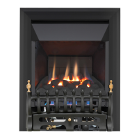
For the top two screws leaving a 2mm gap. See figure 2.
Once you have fitted the screws in place, offer the fire up to the hearth and lift the
fire by a small amount to locate the two keyhole slots on the back of the fire over
the screws. When you lower the appliance, it will now be locked in place. You are
then able to scure the fire to the wall into position with the two bottom fixings.
213mm
213mm
5
2
6
mm
Figure 1
GB IE
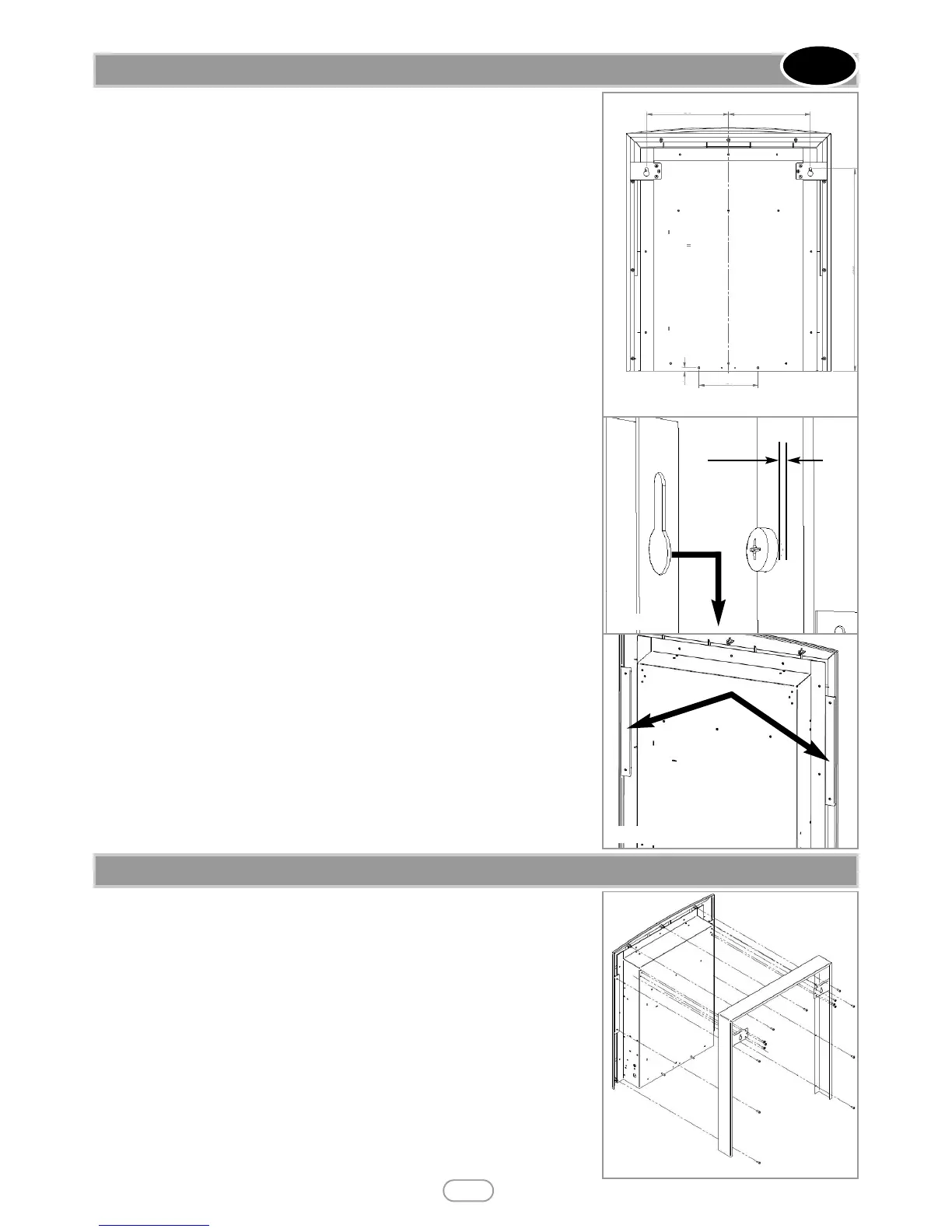
7.0 REMOVING THE APPLIANCE SPACER FRAME
Tools required: Phillips screwdriver.
Step 1 - Ensure the appliance is disconnected at the supply socket before under-
taking the required work.
Step 2 - Remove the fifteen screws from the rear spacer located at the rear of the
appliance.
Step 3 - Remove the outer spacer frame.
Figure 4
Figure 2
Figure 3
9mm
154mm