25
SPECIFICATIONS
MIC INPUT RESPONSE
• Gain range = 0 dB to 60 dB continuously variable
• Input impedance = 50 Ω to 3K3 Ω continuously
variable
• EIN = 128 dB measured at 60 dB of gain with 150 Ω
terminating impedance and 20 Hz/22 kHz bandpass
filter
• THD at minimum gain (0 dB) = 0.0004% measured
with +16 dBu input signal and with a 20 Hz/22 kHz
bandpass filter
• THD at maximum gain (60 dB) = 0.003% measured
with a –36 dBu input signal and with a 20 Hz/22 kHz
bandpass filter
• THD at maximum input level (26.5 dBu) = 0.005%
measured with a 20 Hz/22 kHz bandpass filter
• Frequency response at minimum gain (0 dB) = flat at
10 Hz and –2 dB down at 200 kHz
• Frequency response at maximum gain (60 dB) = –2 dB
down at 10 Hz and 200 kHz
• CMRR at full gain (60 dB) = 80 dB
LINE INPUT RESPONSE
• Gain range = -10 dB to +10 dB continuously variable
• Input impedance = 10K Ω from 10 Hz to 200 kHz
• Noise at main output with gain set to 0 dB = -94 dBu
measured with a 20 Hz/22 kHz bandpass filter
• Noise at –10 dBV output with gain at 0 dB = -100 dBu
measured with a 20 Hz/22 kHz bandpass filter
• Signal to noise ratio relative to max headroom (27 dBu)
= 121 dB
• Signal to noise ratio relative to 0 dBfs (+22 dBu) = 116
dB
• THD at unity gain (0 dB) = 0.0006% measured with 0
dBfs (+22 dBu) input signal and with a 20 Hz/22 kHz
bandpass filter
• Frequency response at unity gain (0 dB) = 0.1 dB down
at 10 Hz and –3 dB down at 200 kHz
INSTRUMENT INPUT RESPONSE
• Gain range (High Gain switch out) = 0 dB to 20dB
continuously variable
• Gain range (High Gain switch in) = 20 dB to 40dB
continuously variable
• Input Impedance = > 1 Meg Ω
• Noise at minimum gain (0 dB) = -90 dBu measured
with a 20 Hz/22 kHz bandpass filter
• Noise at maximum gain (40 dB) = -78 dBu measured
with a 20 Hz/22 kHz bandpass filter
• THD at minimum gain (0 dB) = 0.006% measured
with –10 dBu input signal and with a 20 Hz/22 kHz
bandpass filter
• Frequency response at unity gain (0 dB) = 0.5 dB down
at 10 Hz and –1 dB down at 200 kHz
• Frequency response at maximum gain (40 dB) = 6 dB
down at 10Hz and –1dB down at 200KHz
INPUT METER
• 6 LED peak reading meter is calibrated relative to 0
dBfs where 0 dBfs = +22 dBu (the maximum level
which can be correctly converted by the optional
internal A/D converter before overload occurs). The
meter calibration points are as follows: -
Meter panel
calibration value
Equivalent dBu value
0 dBfs +22 dBu (the maximum signal level
the ADC can convert before digital
distortion occurs)
-6 dBfs +16 dBu
-12 dBfs +10 dBu
-18 dBfs +4 dBu (the normal signal level in
an analogue system to allow
headroom for additional processing
such as EQ)
-24 dBfs -2 dBu
-42 dBfs -20 dBu
CHANNEL INSERT
Unbalanced input and output on balanced (TRS)
socket as follows:-
Tip = Send (Output)
Ring = Return (Input)
Signal level equivalent to –6dB below normal operating
level.
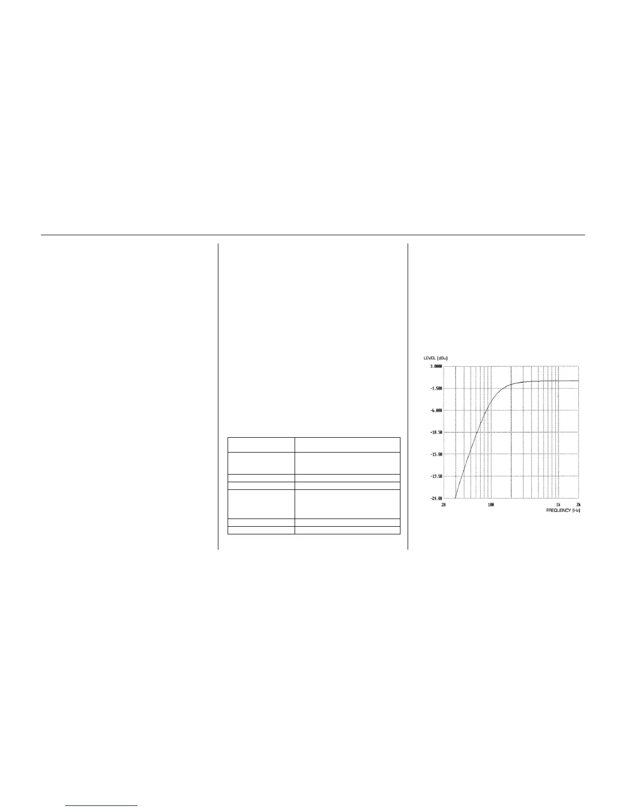
HIGH PASS FILTER
• Roll off = 12 dB per octave 2 pole filter
Frequency range:
Cut off frequency: -3 dB at 120 Hz
-6 dB at 85 Hz
-12 dB at 56 Hz