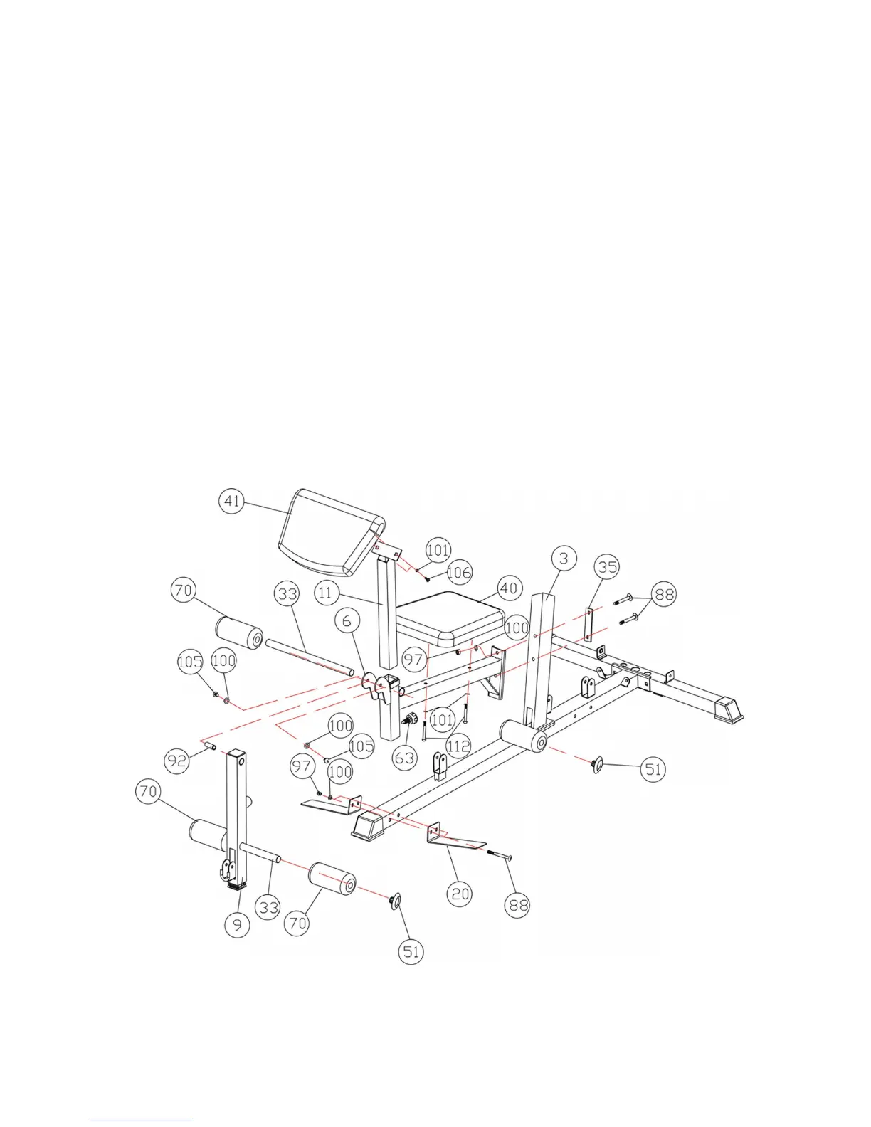
STEP 4
A) Attach the Seat Support Frame (6#) to the Front Vertical Frame(3#) and Secure them
with two pcs M10*90 Carriage Bolt(88#), one pc Bracket(35#) two pcsφ10
Washers(100#), and two pc M10 Aircraft Nut(97#).
B) Attach the Leg Developer (9#) to the front of the Seat Support Frame(6#) and
Secure them with two pcs M10*16 Allen Bolt(105#), two pcs φ10
Washers(100#),one PC Swivel Axle(92#). Do not tighten the bolts and make sure the
Leg developer can swivel freely. Insert the Arm Curl Stand (11#) into the top
opening of the Seat Support Frame(6#) and choose different height with lock
knob(63#).
C) Place the Seat Pad (40#) onto the Seat Support Frame(6#), and Secure them with
Two pcs M8*65 Allen Bolts(112#), two pcs φ8 washers(101#) . Place the Arm Curl
Pad (41#) onto the Arm Curl Pad Support(11#) and Secure them with 2pcs M8*16
Allen Bolts(106#), Twoφ8 washers(101#).
D) Insert one pc Foam Roll Tube(33#) into the hole of Seat Support Frame (6#)halfway,
another Roll Foam Tube into the hole of Leg Developer(9#). Place the four Foam
rolls(70#) onto the Foam Roll Tube (33#) from two ends. And then insert the four
End Cap (51#) into the Foam Roll Tube(33#).
E) Attach 2pcs Foot Plate(20#) to the Main Base Frame(1#), Secure them with 2pcs
Carriage Bolts(88#),two Pcsφ10 washers(100#) and M10 Aircraft Nuts(97#)
9