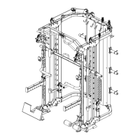
Important: Study and follow the diagram carefully.
A Attach the 2950 mm Upper cable (86#) through the opening of the upper frame (2#). Place 1PC
Pulley (103#) below the cable and secure the 1st pulley using 1PC M10 × 45 Allen bolt (61#) ,2PC
ø10 washer (69#) and 1×M10 Aircraft nut (68#).
B Draw the cable backwards and place the 2st pulley below the cable , Secure the pulley with the
same way in A.
C Draw the cable around the pulley and front , Place the 3st pulley below the cable and secure it with
1PC M10×140 Allen bolt (56#), 2PC ø10 washer (69#) and 1×M10 Aircraft nut (68#).
D Draw the cable around the pulley and backwards,Place the 4st pulley below the cable and secure it
with the same way in A.
E Draw the cable around the pulley and downwards,Place the 5st pulley onto the cable, Secure the
pulley with double floating pulley bracket(36#) together with the way in A.
F Draw the cable around the pulley and upwards ,Place the 6st pulley below the cable and secure
them with the 1PC M10
×
65 Allen bolt (59#) ,2PC bushing (72#) and 1pc M10 Aircraft nut (68#).
.
G Draw the cable around the pulley and downwards,thread the end of the upper cable to the top
opening of the selector rod at least 5 laps to keep safe.