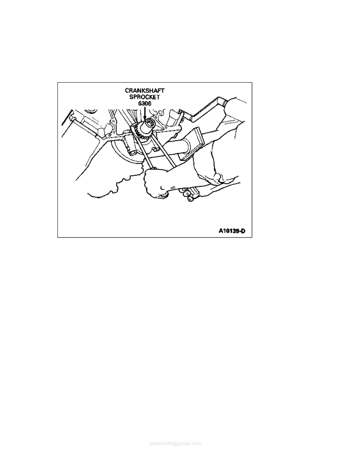
large screwdrivers. Use care to prevent damage to finished areas on the crankshaft (6303).
Remove timing chain/belt (6268), camshaft sprocket (6256) and camshaft (6250) as an assembly.
17. Remove camshaft thrust plate bolts and camshaft thrust plate (6269).
18. Remove camshaft. Use care to prevent damage to camshaft bearing surfaces and lobes.
19. Rotate engine (6007) 180 degrees.
20. Remove oil pump (6600).
21. NOTE: The cylinder number is stamped on the top of each piston (6108). Matched letters are
stamped on the sides of corresponding rod and cap.
NOTE: Before removing the pistons, inspect the top of the cylinder bores. If necessary,
remove the ridge and/or carbon deposits from each cylinder using a suitable ridge remover.
Before the ridge or deposits are removed turn the crankshaft until the piston, pin and ring
(6102) is at the bottom of the bore. Cover the piston with a clean shop towel to collect the
cuttings. After the cutting operation, turn thecrankshaft until the piston is at the top of bore
and remove the shop towel and the cuttings. Never cut into the ring travel area in excess of
0.794mm (0.03125 inch).
Remove connecting rod nuts and tap out piston, pin and ring and connecting rod (6200) with a
wooden hammer handle. Nuts should go on the same stud they were removed from. Make sure caps
are reinstalled on same rod and orientated correctly.
22. The location of each piston, connecting rod bearing (6211), and rod cap should be noted. When the
engine is assembled, each component should be installed in its original position.
file://C:\TSO\tsocache\VDTOM_5368\SVK~us~en~file=SVK31B43.HTM~gen~ref.HTM
 Loading...