GENERAL
MAINTENANCE
AND ADJUSTMENTS
SECTION
G
14
\
T
PANEL
OR WARNING LIGHT
BULB
1
.
Remove the
screws securing the instrument
panel to the rear
hood assembly
and pull
the instrument panel
outwards. If required,
better access may
be
ohtained
by detaching the
proofmeter drive cable.
2,
Remove the bulb
socket from the rear of
the panel and fit
a new bulb.
Re-assemble
in the reverse
order.
FUSE REPLACEMENT
Nib
slandard
tractor lighting
circuit is protected
by a 15 amp
fuse
and
the
I
itnidge
type fuse holder,
(2)
Figure G15, is
located close to the lighting
swilch, behind the
fuel tank shroud.
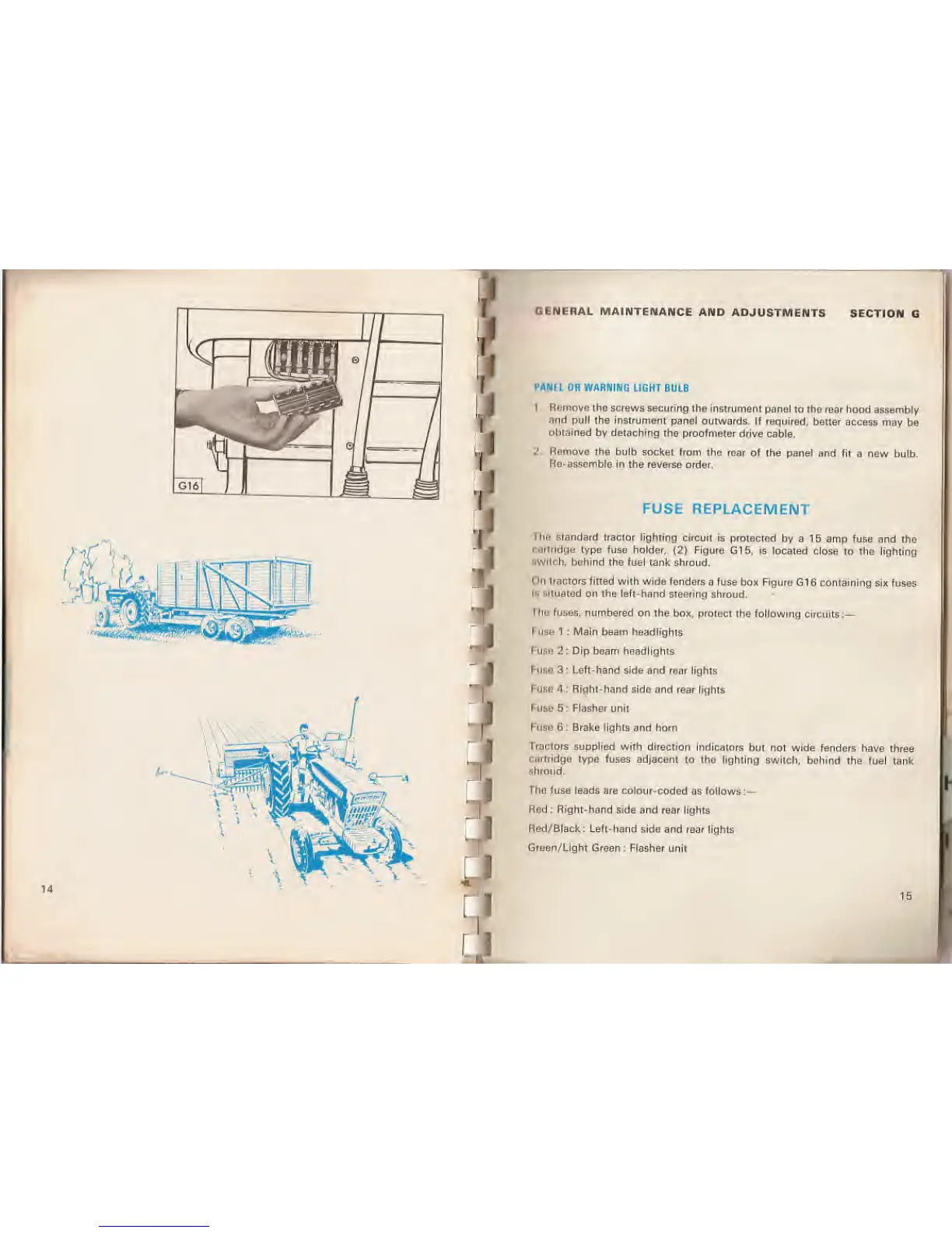
(in
tiactors fitted
with wide fenders
a fuse box Figure G16 containing
six fuses
Is
situated
on the left-hand steering
shroud.
rhe fuses, numbered
on the box, protect the following
circuits:
—
I
use 1 : Main beam headlights
Fuse 2: Dip beam headlights
Fuse 3 ; Left-hand
side
and rear lights
Fuse
4 : Right-hand side and
rear
lights
Fuse 5: Flasher
unit
Fuse
6 : Brake lights and horn
Tractors supplied with
direction indicators
but not wide fenders
have three
cartridge type
fuses adjacent to tho lighting
switch, behind
the fuel tank
shroud.
The fuse
leads are colour-coded
as follows:—
Red : Right-hand
side and rear lights
Red/Black: Left-hand side and
rear lights
Green/Light Groen
: Flasher unit
15
: r