SECTION
H OPTIONS
AND ACCESSORIES
(d) Secure the other stop lug.
(e)
Move the RIGHT-HAND
rim outwards using the above
procedure with
low reverse gear selected and the
left-hand brake pedal held down.
(f) Using the
special spanner provided tighten the locking
nuts
(1).
On the
Ford 4000 and 5000
tighten only the marked nuts
with the wheel in the
original position as (a).
Tighten the nuts gradually,
ensuring that the
exposed
thread outside each nut is the
same.
To decrease the
width of the
rear
track
within one of the two ranges:
Use the
above procedure selecting
directly opposite gears to those stated
in
stages (c) and (e).
To change from
one width range to
the other:
FORD 2000
AND 3000
Interchange the left-hand and right-hand
wheel assemblies ensuring
that the
'Vee'
of the tread is pointing in the
forward travel direction.
F0R0 4000 AND 5000
(Figure H1Q)
(a) Loosen and mark the
adjusting screw lock nuts
{1
).
(b)
Remove the support
blocks and position them, one at a
time, on the
opposite side of the disc
(5).
Tighten the support
block bolts checking that they are
well seated against
the disc face and edge.
(c)
Move the wheel to position the
unmarked blocks
(6)
at the top;
remove
and position
them on the
opposite
side
of the disc. Tighten the block
bolts.
(d)
To increase or decrease the
track width proceed as
before.
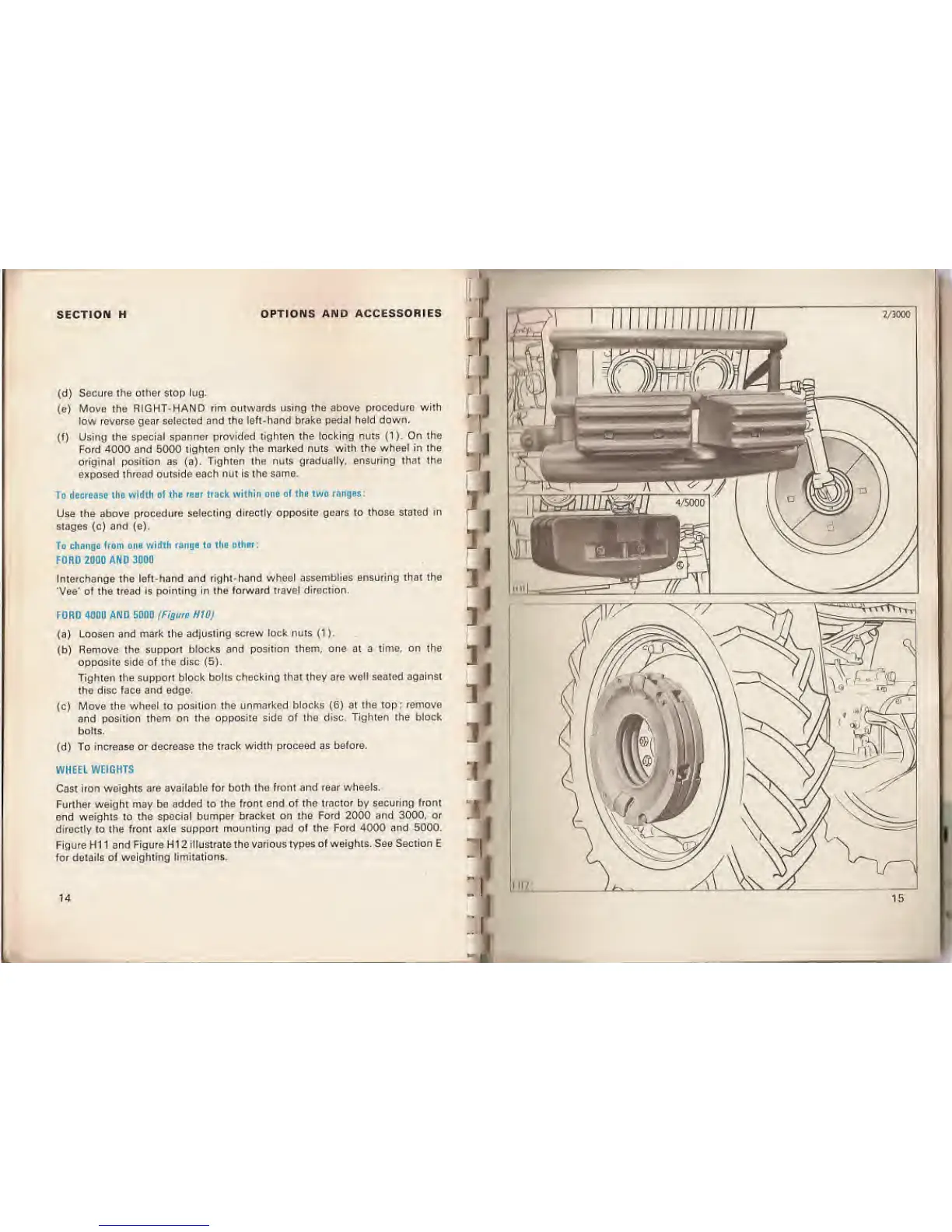
WHEEL
WEIGHTS
Cast iron
weights are available
for both the front and rear wheels.
Further weight
may
be
added to the front end
of the tractor by securing
front
end weights to the special
bumper bracket on the
Ford 2000 and 3000, or
directly to the front axle
support mounting pad of the Ford 4000
and 5000.
Figure H1 1
and Figure H1 2 illustrate the
various types of weights. See Section E
for details of weighting
limitations.
14