2-4
GROUP 2 - Brakes
wheels).
4.
Release the parking brake, and
check to make sure that the brake
shoes return to the fully released po-
sition.
5.
Depress the parking brake pedal
to the third notch. Under normal con-
ditions, this will hold the vehicle
satisfactorily.
6. Release the parking brake again,
and check as in step 4.
7.
If the rear brakes do not fully
release, check the cables for kinks
or binds. Free the cables as required.
#16 GAUGE
SHEET STEEL
2%'
MIDLAND-ROSS
0.980-0.995 __,
MUSTANG
COUGAR, FALCON,
0.970-0.980
BENDIX
*~ 0.980-0.995
l
H1208-D
FIG. 4—Push Rod Gauge
Dimensions
POWER BRAKE MASTER
CYLINDER PUSH ROD
ADJUSTMENT
The push rod is provided with an
adjustment screw to maintain the cor-
rect relationship between the booster
control valve plunger and the master
cylinder. Failure to maintain this
relationship will prevent the master
cylinder piston from completely re-
leasing hydraulic pressure and can
cause the brakes to drag.
The adjustment screw is set to the
correct height at the time of original
assembly of the power unit. Under
normal service the adjustment screw
does not require any further attention
providing the original push rod assem-
bly remains in the original unit.
To check the adjustment of the
screw, fabricate a gauge of the di-
mensions shown in Fig. 4. On the
Midland-Ross booster, remove the
master cylinder and air filter assem-
bly and push the bellows back into
the booster body. Re-install the air
filter directly against the booster
body, and then place the gauge
against the master cylinder mounting
surface of the air filter assembly as
shown in Fig. 5 or 6. The push rod
screw should be adjusted so that the
end of the screw just touches the in-
ner edge of the slot in the gauge.
AIR FILTER
action. Bleed the hydraulic system
after it has been properly connected,
to be sure that all air is expelled.
H1349-A
FIG. 5—Push Rod Adjustment—
Midland-Ross
Do not set up side forces on the
push rod as it may break the valve
plunger.
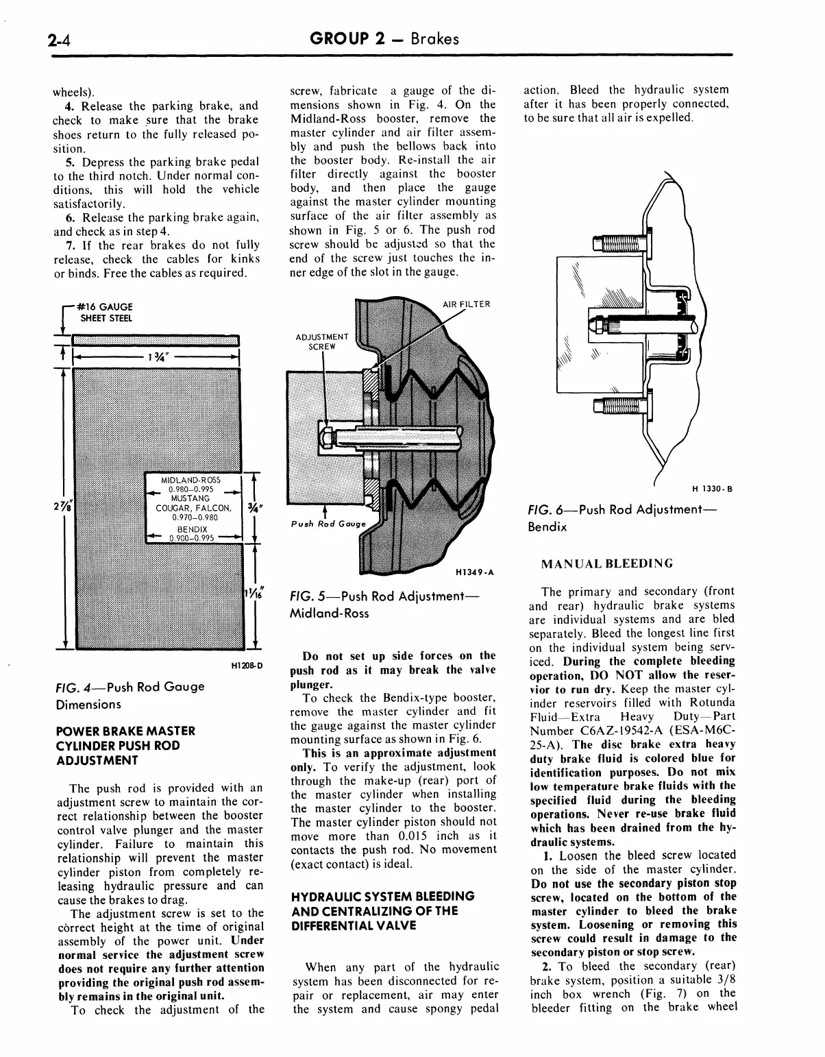
To check the Bendix-type booster,
remove the master cylinder and fit
the gauge against the master cylinder
mounting surface as shown in Fig. 6.
This is an approximate adjustment
only. To verify the adjustment, look
through the make-up (rear) port of
the master cylinder when installing
the master cylinder to the booster.
The master cylinder piston should not
move more than 0.015 inch as it
contacts the push rod. No movement
(exact contact) is ideal.
HYDRAULIC SYSTEM BLEEDING
AND CENTRALIZING OF THE
DIFFERENTIAL VALVE
When any part of the hydraulic
system has been disconnected for re-
pair or replacement, air may enter
the system and cause spongy pedal
H 1330-B
FIG. 6—Push Rod Adjustment—
Bendix
MANUAL BLEEDING
The primary and secondary (front
and rear) hydraulic brake systems
are individual systems and are bled
separately. Bleed the longest line first
on the individual system being serv-
iced. During the complete bleeding
operation, DO NOT allow the reser-
vior to run dry. Keep the master cyl-
inder reservoirs filled with Rotunda
Fluid—Extra Heavy Duty—Part
Number C6AZ-19542-A (ESA-M6C-
25-A).
The disc brake extra heavy
duty brake fluid is colored blue for
identification purposes. Do not mix
low temperature brake fluids with the
specified fluid during the bleeding
operations. Never re-use brake fluid
which has been drained from the hy-
draulic systems.
1.
Loosen the bleed screw located
on the side of the master cylinder.
Do not use the secondary piston stop
screw, located on the bottom of the
master cylinder to bleed the brake
system. Loosening or removing this
screw could result in damage to the
secondary piston or stop screw.
2.
To bleed the secondary (rear)
brake system, position a suitable 3/8
inch box wrench (Fig. 7) on the
bleeder fitting on the brake wheel

 Loading...