32 Fortinet Inc.
Rear panel features Getting started
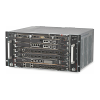
Figure 7: FortiGate-4000S rear panel
Power supplies and power connections
The FortiGate-4000 chassis contains 7 power supply modules. Each power supply
can provide a maximum of 350 watts for a total of 2100 watts, in 6+1 hot-swap
redundant configuration that includes load balancing. The voltage range is 100-230
Vac auto range.
The power connections supply AC power to the power supplies. Connect the three
power connections to three separate power outlets. Use the power switch on the
power connector module to turn the FortiGate-4000 chassis power on and off.
A power supply module is powered on when its power on LED turns green.
Figure 8 illustrates the power supply modules and the power connectors.
Figure 8: Power supply modules and power connectors
LAN 2LAN 1
ONON OFFOFF
ERRERR
Management
module
External ethernet
switched interface
modue
Cooling fan trays
LAN 1LAN 2COM
SFP
SFP HiGig OUT HiGig IN
ON OFF
LAN 1LAN 2COM
SFP
SFP HiGig OUT HiGig IN
ON OFF
Power
connectors
Chassis
power
switch
Power supply
modules (7)
Power switch
Power on LED
Fan housing
Locking handle
Internal ethernet
switched interfa
module
10/100 out of ba
management
module
ONON OFFOFF
ERRERR
Power supply
modules (7)
Power switch
Power on LED
Fan housing
Locking handle
Power
connectors
Locking strip
Locking screw
Locking screw

 Loading...