Do you have a question about the Fostex A-8 and is the answer not in the manual?
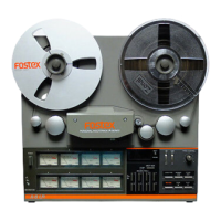
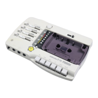
Buttons for tape movement, recording, and zero return functions.
Group select, MONITOR, counter, EDIT, NR, PITCH, CUE, RECORD LEDs.
Reel clamper, remote jacks, I/O jacks, and power cord.
Explains LSI processing and circuits for basic transport and reset.
Details circuits for remote punch, capstan, solenoids, and reel motors.
Explains tape counter, LED indicators, and record track selection circuits.
Instructions for cleaning heads, guides, pinch roller, and capstan.
Demagnetizing heads/guides and testing brakes, pinch roller, amplifier.
Lists necessary test equipment for special maintenance.
Step-by-step instructions for removing major internal components.
Procedures for adjusting pinch roller, brakes, tape tension, wow/flutter, and tape speed.
Calibration of Dolby, frequency response, bias, recording level, S/N, THD, crosstalk.
Defines codes for screws, nuts, bolts, and washers used in assembly.
Detailed lists of components for various PCB assemblies and the overall unit.
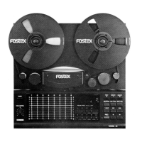
Buttons for tape movement, recording, and zero return functions.
Input monitor, track selection, counter, EDIT, NR, PITCH, CUE, RECORD LEDs.
Reel clamper, remote jacks, I/O jacks, and power cord.
Detailed procedures for Dolby, frequency response, bias, recording level, S/N, THD, and sync crosstalk.
Lists components for the Connector Board PCB, including ICs, resistors, capacitors.
Lists components for the R/P Amplifier PCB (19cm/s version).
Lists various resistors, capacitors, and trimmer pots.
| Brand | Fostex |
|---|---|
| Model | A-8 |
| Category | Recording Equipment |
| Language | English |