605-01-3 67 9
NOTICE: Do not discard any OEM bolts, many are
reused with the new FOX shock assembly.
12. If an aftermarket UCA is required with the FOX
shock kit, install the UCA now. Follow the company’s
required specifications. After installation, continue
to step 16.
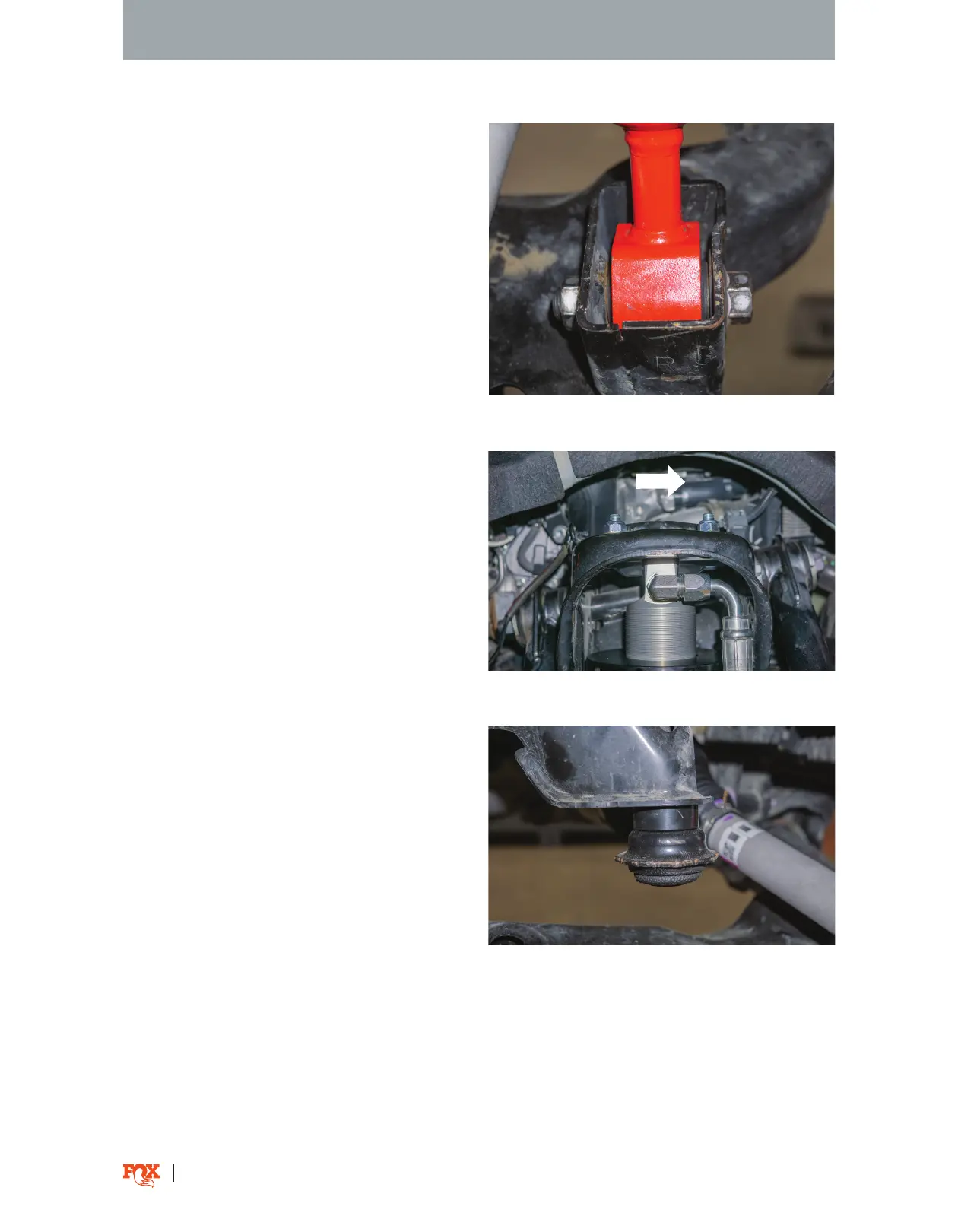
Fig. 9: The hose fitting faces outboard.
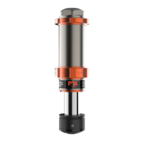
Fig. 10: Install the bump stop spacer if
preload is added.
13. Install the new shock assembly with the hose
fitting pointed outboard (Fig. 9). Loosely install the
provided top hat nuts, washers, and OEM lower
mount bolt.
14. Once the shock is oriented, torque the top hat
nuts to 24 ft-lbs. Torque the lower mount bolt to
OEM specification.
FOX SHOCK INSTALL
Fig. 8: Remove the bolt from the lower control arm.
11. Take o the bolt connecting the shock to the
lower control arm (Fig. 8). Remove the stock shock
assembly.
NOTICE: The vehicle’s ride height is set for 2.25”
of lift (level) on a stock weight truck. If more lift
is desired, up to 3/8” preload can be added by
removing the spring, loosening the pinch bolt, and
spinning the preload collar. 1/4” of preload added
is equivalent to about a 1/2” of lift. If any preload
is added, the provided bump stop spacer must be
installed (Fig. 10) to prevent coil bind. If more than
3/8” additional preload is added an aftermarket
bumpstop spacer or longer bump stop will be
required.
FRONT OF VEHICLE