605-01-3 67 10
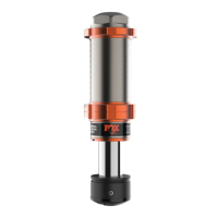
Fig. 12: Diagram of reservoir and bracket interface.
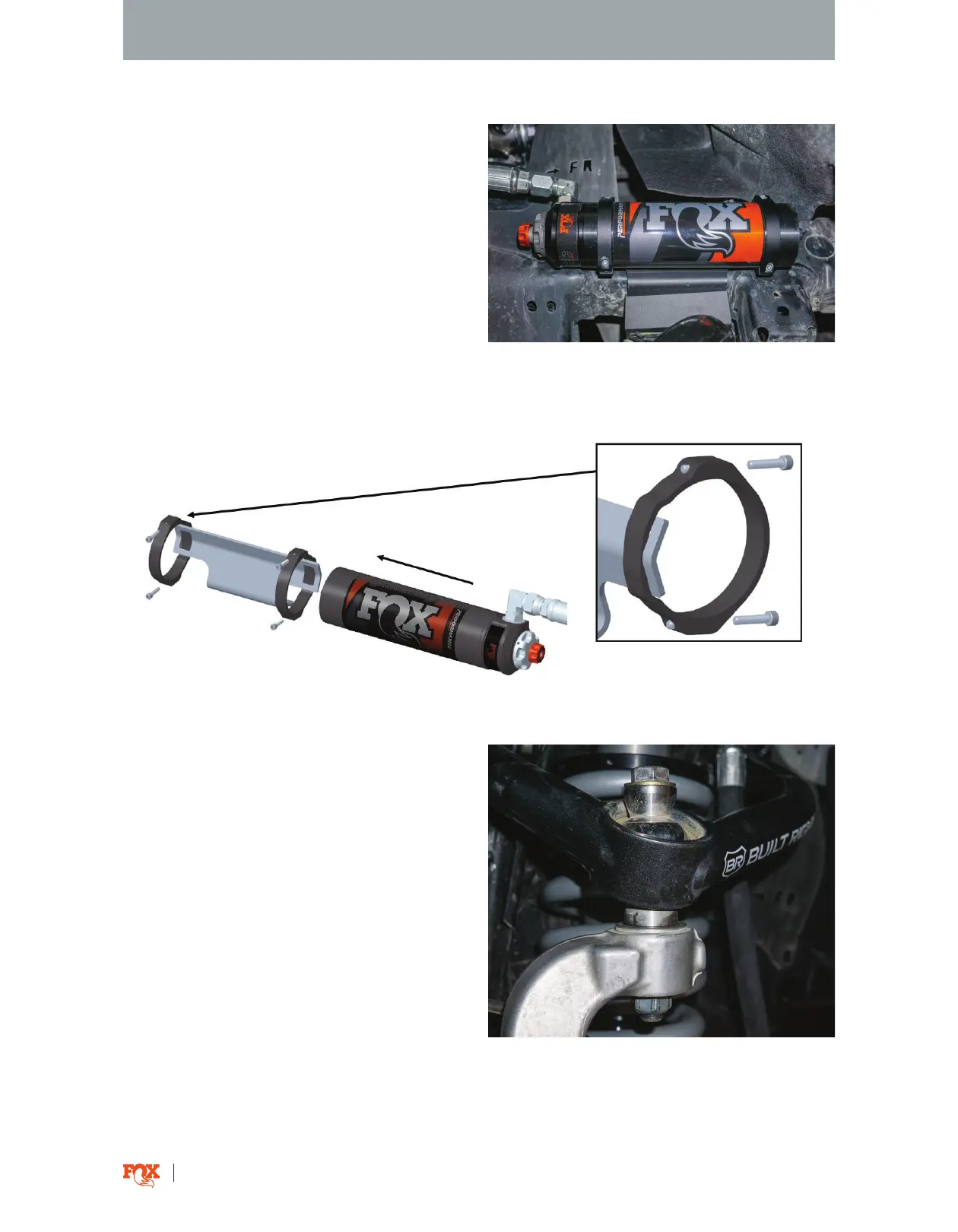
Fig. 11: Mounted reservoir.
16. Reattach the UCA to the upright with the ball
joint bolt and torque to OEM specification or the
UCA manufacturer’s specs (Fig. 13).
Fig. 13: Reattach UCA to the upright.
NOTICE: Minor trimming of the fender liner or air
dam may be required for reservoir fitment.
15. Attach the reservoir to the mounting bracket
with the provided reservoir clamps and screws.
(Fig. 11). Loosely pre-assemble the upper clamp
assembly. Tighten the clamp to 50% when the
reservoir is centered with proper hose positioning.
Slide the bottom half of the clamp into position for
the second clamp assembly. Tighten both screws on
each clamp assembly evenly until tight. Complete
the installation and torque to 19 in-lbs (Fig. 12).
NOTICE: Utilize the slots in the bracket to locate the
clamps. Do not feed the clamps through the slots in
the bracket.