7320 IFL Installation and User’s Guide
Introduction to the 7320 IFL
Foxcom Proprietary Information 11
Document No. 93-005-28-C
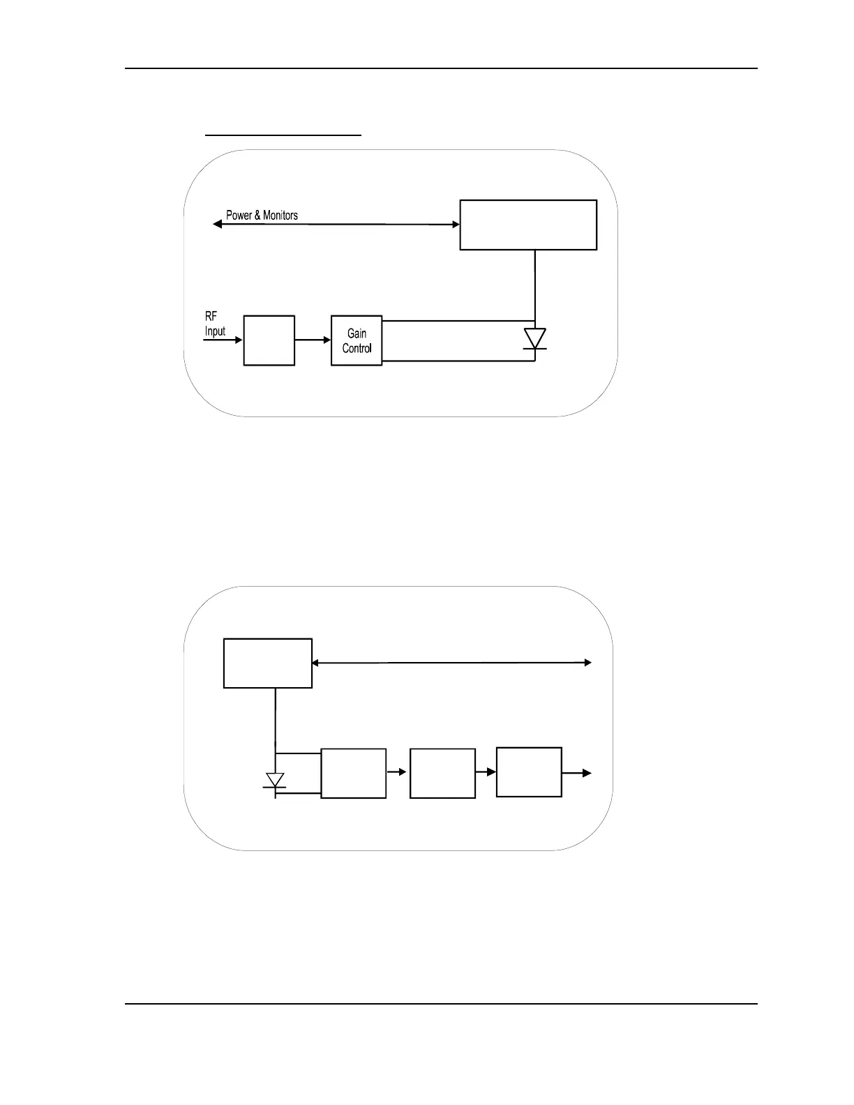
2.3 Block Diagrams
Laser
Optical Power &
Temperature
Control
Pre-
Amp
Figure 4 - Transmitter Block Diagram
The 7320T Transmitter accepts RF input signal levels ranging from -40 to -20 dBm
total power (i.e. at 10 channel loading this is equivalent to -50 to -30 dBm per
channel). The unit amplifies the signal, and feeds it to a laser diode which linearly
converts the broadband RF signal to light intensity.
Power & Monitors
Preamp
Postamp
Gain
Control
Output
Photodiode
Bias &
Optical Power
Monitor
Figure 5 - Receiver Block Diagram
The 7320R Optical Receiver receives the optical intensity signal, and linearly converts
the signal back to RF. The Receiver then amplifies and reproduces the L-Band RF
signal.