7320 IFL Installation and User’s Guide
Product Technical Description
Foxcom Proprietary Information 21
Document No. 93-005-28-C
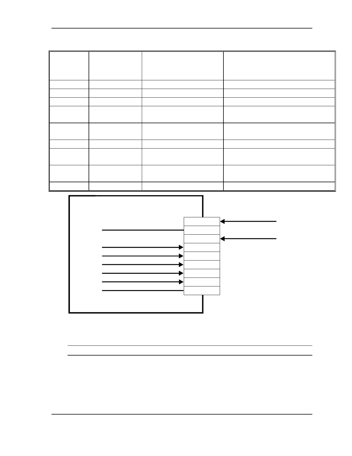
Table 4 - 7320R Receiver Pinout
Standalone
9 Pin
Connector
Rackmount 6
Pin Back Panel
Connector
Function Description
1 +15V 230 mA
2 Not Used
3 Power Ground DC Return
4 4 RF Signal Strength
Monitor
RF Signal Strength Indicator;
Range 0.25 to 2V
5 6 Optical Power Input Level
Monitor
1V/mW Optical Power Received
6 1 Spare Not Used
7 2 RF Alarm Open collector interface. Sinks
current when RF level is low.
8 3 Optical Power Alarm Open collector interface. Sinks
current when optical level is low.
9 5 Spare Not Used
9 Pin D-Type Male Connecter
Power Ground
+15V Power
1
2
3
4
5
6
7
8
9
7320R Receiver
Not Used
RF Signal Strength Monitor
Optical Power Monitor
Not Used
AGC Alarm
Optical Alarm
Not Used
Figure 8 - System 7320 Receiver Pinout
CAUTION
When monitoring the voltage outputs use only a high resistance DVM.