7320 IFL Installation and User’s Guide
Product Technical Description
Foxcom Proprietary Information 20
Document No. 93-005-28-C
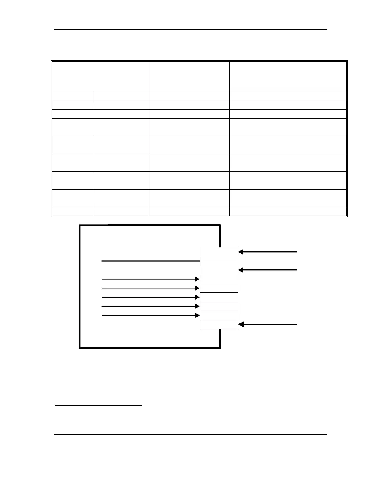
Table 3 - 7320T Transmitter Pinout
Standalone
9 Pin
Connector
Rackmount 6
Pin Back Panel
Connector
Function Description
1 +15V Power 300 mA
4
(excluding LNB Option)
2 Not Used
3 Power Ground DC Return
4 4 RF Signal Strength
Monitor
RF Signal Strength Indicator;
Range 2 - 10V
5 6 PDI Measures Laser Optical Power;
Range -3.0 to -4V
6 1 LSRI Measures Laser Bias;
Range -4.5 ± 0.2V
7 2 RF Alarm Open collector interface. Sinks
current when RF level is low.
8 3 LSR Alarm Open collector interface. Sinks
current when optical level is low.
9 5 LNB Bias (optional) External LNB Bias
9 Pin D-Type Male Connecter
Power Ground
+15V Power
1
2
3
4
5
6
7
8
9
7320T Transmitter
Laser Current Monitor
RF Signal Strength Monitor
Laser Photodiode Current Monitor
Not Used
AGC Alarm
LSR Alarm
External LNB Bias
Figure 7 - System 7320 Transmitter Pinout
4
400 mA below 10
0
C