EasyManuals Logo

Foxconn H55MXV LE User Manual

Foxconn H55MXV LE
72 pages
To Next Page IconTo Next Page
To Previous Page IconTo Previous Page
Page #11 background imageLoading...
Page #11 background image
1
4
1-2 Layout
Note : The above motherboard layout is for reference only, please refer to the physical
motherboard for detail.
1. 4-pin ATX 12V Power Connector
2. SYS_FAN1 Header
3. PCI Express x16 Slot
4. PCI Express x1 Slot
5. PCI Slots
6. Front Audio Connector
7. Speaker Connector
8. S/PDIF Out Connector
9. Intel
®
ME Jumper
10. Front USB Connectors
11. Clear CMOS Jumper
12. TPM Connector
13 Chipset: Intel
®
H55
14. SATA Connectors
15. Front Panel Connector
16. 24-pin ATX Power Connector
17. CIR Connector
18. Chassis Intrusion Alarm Header
19. COM1 Connector
20. DDR3 DIMM Slots
21. CPU_FAN Header
22. LGA1156 CPU Socket
1
15
7
36 24
16
5
12
14
13
17
19
9
10
11
18
20
21
8
22

Questions and Answers:

Question and Answer IconNeed help?

Do you have a question about the Foxconn H55MXV LE and is the answer not in the manual?
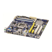
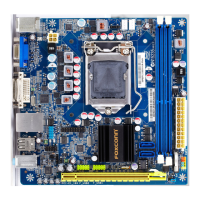
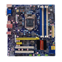
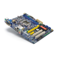
Foxconn H55MXV LE Specifications

General IconGeneral
Form FactorMicro ATX
CPU SocketLGA 1156
Memory TypeDDR3
Maximum Memory8 GB
PCIe 2.0 x1 Slots1
USB Ports (Rear)4
ChipsetIntel H55
Memory Slots2
Expansion Slots1 x PCIe x1
AudioRealtek ALC662
LANRealtek RTL8111DL Gigabit Ethernet
Video OutputsVGA
USB Ports8 (4 rear, 4 via headers)
VGA PortYes

Related product manuals