10
2
2-3 Install other Internal Connectors
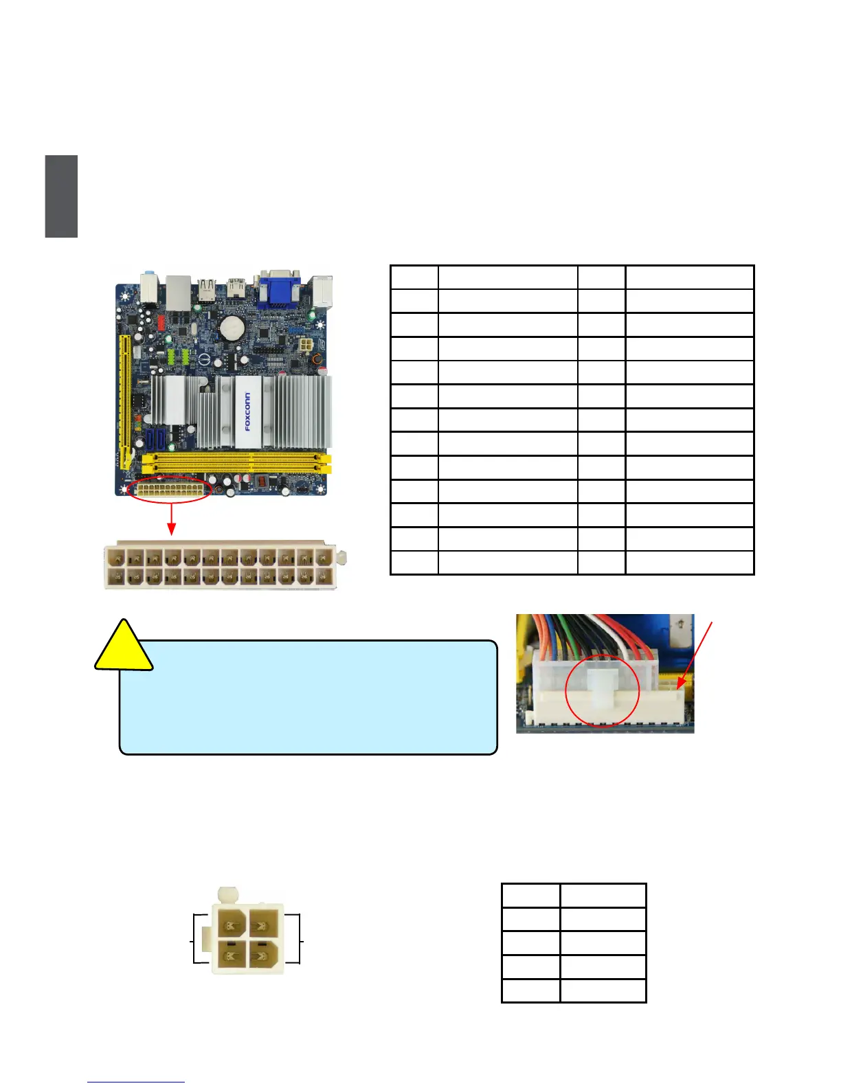
Power Connectors
This motherboard uses an ATX power supply. In order not to damage any device, make sure all the
devices have been installed properly before applying the power supply.
24-pin ATX power connector : PWR2
PWR2 is the ATX power supply connector. Make sure that the power supply cable and pins are
properly aligned with the connector on the motherboard. Firmly plug the power supply cable into the
connector and make sure it is secure.
4-pin ATX 12 V Power Connector : PWR1
Connect the 4-pin ATX 12V power supply to PWR1 and provides power to the CPU.
Pin # Denition Pin # Denition
1 3.3V 13 3.3V
2 3.3V 14 -12V
3 GND 15 GND
4 +5V 16 PS_ON(Soft On/Off)
5 GND 17 GND
6 +5V 18 GND
7 GND 19 GND
8 Power Good 20 NC
9 +5V SB(Stand by +5V) 21 +5V
10 +12V 22 +5V
11 +12V 23 +5V
12 3.3V 24 GND
PWR2
24
13
12
1
We recommend you using a 24-pin power supply.
If you are using a 20-pin power supply, you need
to align the ATX power connector according to
the picture.
C
A
U
T
I
O
N
!
20-Pin Power
Pin No. 24
Pin # Denition
1 GND
2 GND
3 +12V
4 +12V
3 1
GND
+12V
4 2
PWR1
 Loading...