Pin configuration is as follows:
- LINK IN
- PCS
Ground Terminal
This terminal is used to connect the battery to the earth for safety purposes.
In parallel mode, this terminal can also be used to connect to parallel battery.
Handle
The handle is used to carry or move the battery.
DC Switch
Power switch, battery charge and discharge circuit switch.
DC+
Connect bat + of inverter.
DC -
Connect bat - of inverter.
Power Switch
System power on switch, press this switch for about 3s, the system starts to work.
BMS Status LED and SOC LED
LED display specific alarm information and battery system power.
5.2 Monitoring Methods
Battery system remote monitoring available via inverter app.
6. Installation
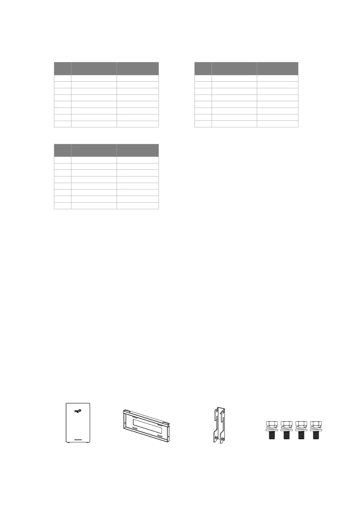
6.1 Items in the package
Please check if following items are including with the package:
Battery×1(A2) Bracket(wall)×1(B2) Bracket(battery)×2(C2) M6*12 Screw×4(D2)