• Grid Connection
This series inverters are designed for single-phase grid. Voltage range is 220/230/240V; frequency is
50/60Hz. Other technical requests should comply with the requirement of the local public grid.
WARNING!
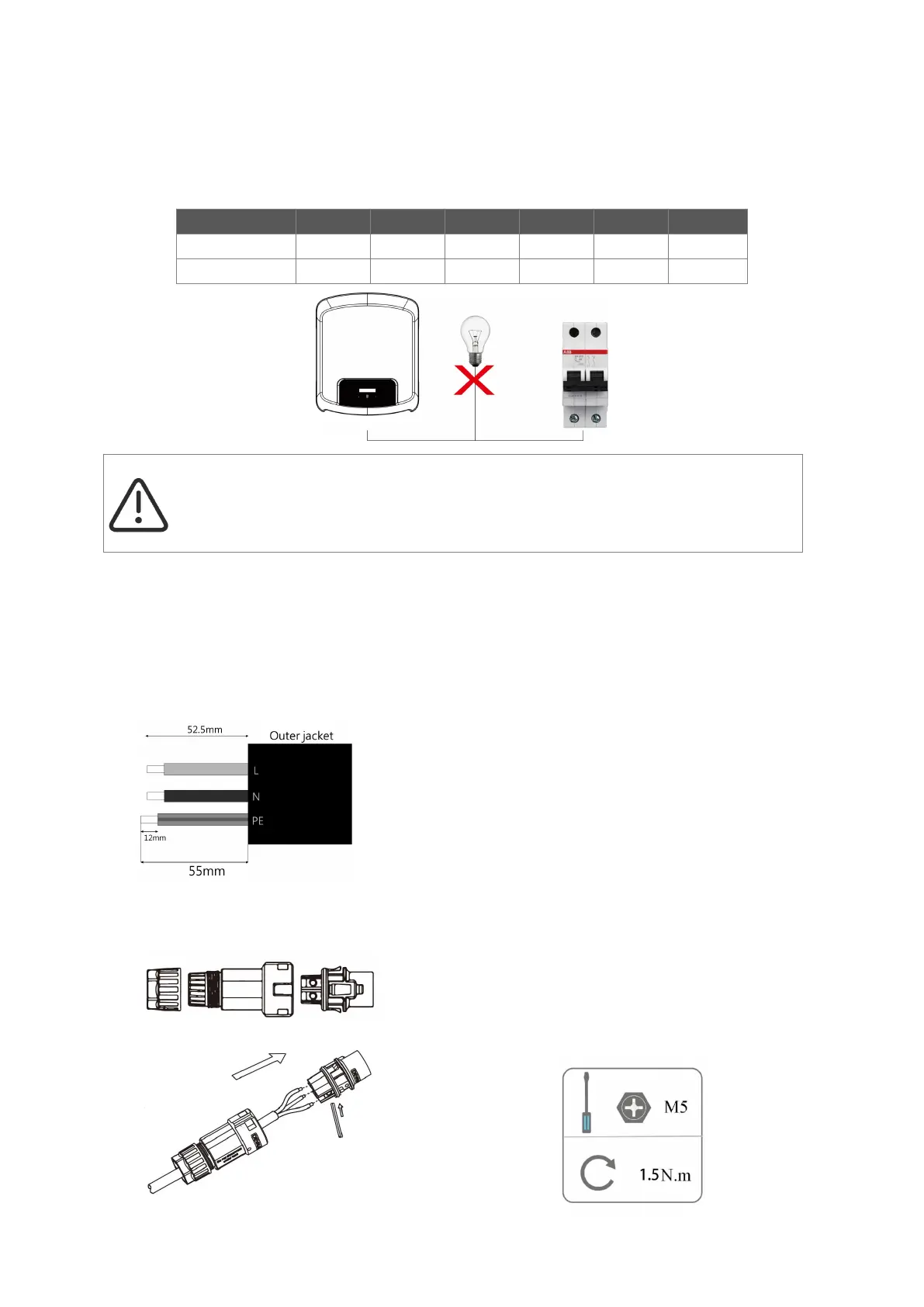
A micro-breaker for max output overcurrent protection device shall be installed between inverter and
grid, and the current of the protection device is referred to the table above, any load SHOULD NOT
be connected with the inverter directly.
Step 3: AC Wiring
• Check the grid voltage and compare with the permitted voltage range (refer to technical data).
• Disconnect the circuit-breaker from all the phases and secure against reconnection.
• Trim the wires:
-
Trim all the wires to 52.5mm and the PE wire to 55mm.
-
Use the crimping pliers to trim 12mm of insulation from all wire ends as below.
• Separate the AC plug into three parts as below.
-
Hold middle part of the female insert, rotate the back shell to loosen it, and detach it from female inset.
-
Remove the cable nut (with rubber insert) from the back shell.
• Slide the cable nut and then the back shell onto the cable.
L: Brown/Red Wire
N: Blue/Black Wire
PE: Yellow & Green Wire
Note: Please refer to local cable type and color for actual installation.