25
• BMS
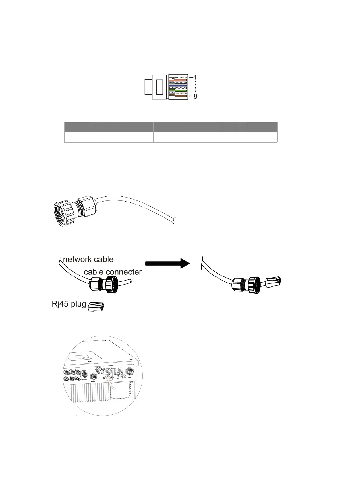
Communication interface between inverter and battery is RS485 or CAN with a Rj45 connector.
PIN 1 2 3 4 5 6 7 8
Definition
/ GND BMS-485B BMS-CANL BMS-CANH / / BMS-485A
Connection steps:
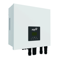
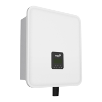
Step 1: Prepare a standard network cable and cable connector, then insert the network cable through the
cable connector.
Step 2: Crimp the cable with a Rj45 plug which is inside of the cable connector.
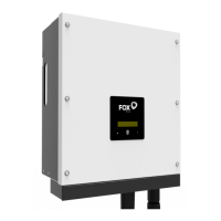
Step 3: Insert the cable connector into BMS port at the bottom of inverter and screw it tightly.