16
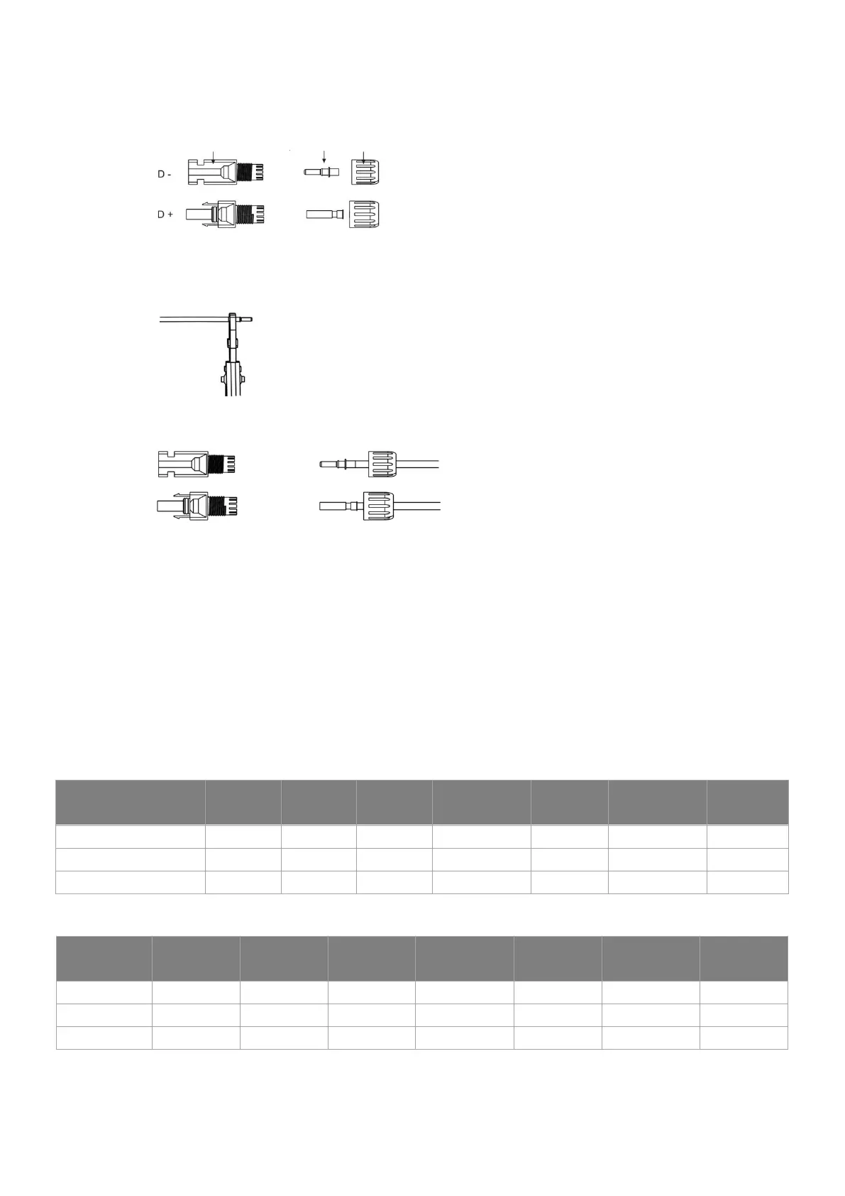
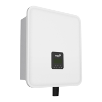
• Separate the DC connector (battery) as below.
Plug Pin contact cable nut
• Insert striped cable into pin contact and ensure all conductor strands are captured in the pin contact.
• Crimp pin contact by using a crimping plier. Put the pin contact with striped cable into the
corresponding crimping pliers and crimp the contact.
• Insert pin contact through the cable nut to assemble into back of the male or female plug. When you
feel or hear a “click” the pin contact assembly is seated correctly.
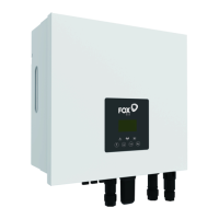
• Unlock the DC connector
- Use the specified wrench tool.
- When separating the DC + connector, push the tool down from the top.
- When separating the DC - connector, push the tool down from the bottom.
- Separate the connectors by hand.
6.3 AC Connection
Step 1: AC String Connection
H1/AC1 series inverters are designed for single-phase grid. Voltage range is 220/230/240V; frequency is
50/60Hz. Other technical requests should comply with the requirement of the local public grid.
Table1: Without EPS Function (internal)
Table2: With EPS Function (internal)
Model
H1-3.0-E
AC1-3.0-E
H1-3.7-E
AC1-3.7-E
H1-4.6-E
AC1-4.6-E
H1-4.6-E1[1]
AC1-4.6-E1[1]
H1-5.0-E
AC1-5.0-E
H1-5.0-E1[1]
AC1-5.0-E1[1]
H1-6.0-E
AC1-6.0-E
Cable (GRID) 4.0mm² 4.0mm² 6.0mm² 6.0mm² 6.0mm² 6.0mm² 6.0mm²
Cable (EPS) 4.0mm² 4.0mm² 6.0mm² 6.0mm² 6.0mm² 6.0mm² 6.0mm²
Micro-Breaker 25A 25A 32A 32A 32A 32A 40A
Model
H1-3.0-E
AC1-3.0-E
H1-3.7-E
AC1-3.7-E
H1-4.6-E
AC1-4.6-E
H1-4.6-E1[1]
AC1-4.6-E1[1]
H1-5.0-E
AC1-5.0-E
H1-5.0-E1[1]
AC1-5.0-E1[1]
H1-6.0-E
AC1-6.0-E
Cable (GRID) 8.0-10.0mm² 8.0-10.0mm² 8.0-10.0mm² 8.0-10.0mm² 8.0-10.0mm² 8.0-10.0mm² 8.0-10.0mm²
Cable (EPS) 4.0mm² 4.0mm² 6.0mm² 6.0mm² 6.0mm² 6.0mm² 6.0mm²
Micro-Breaker 50A 50A 63A 63A 63A 63A 63A