17
Note:
1. If you don't use the EPS function, the wiring conduct core section can refer to the parameters of
table 1.
2. If you use the EPS function,the wiring conduct core section can refer to the parameters of table 2.
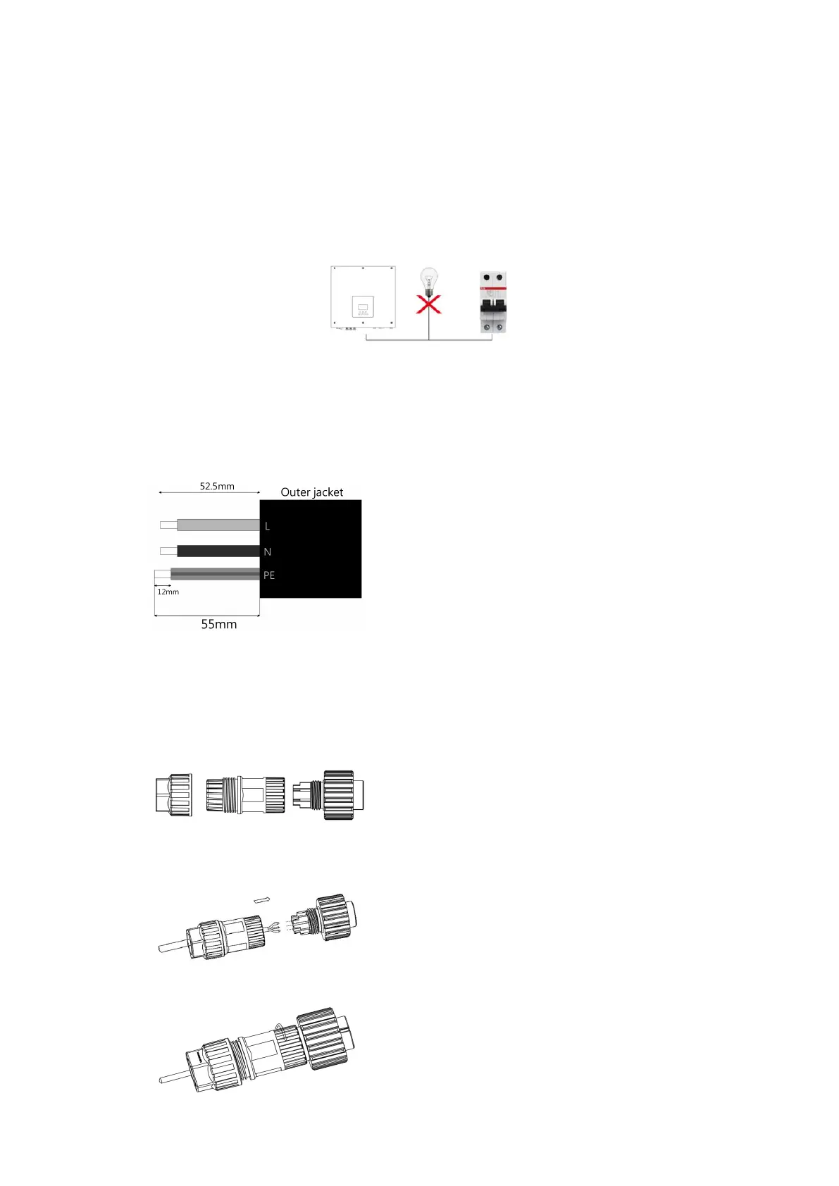
3. A micro-breaker for max output overcurrent protection device shall be installed between inverter
and grid, and the current of the protection device is referred to the table above, any load SHOULD
NOT be connected with the inverter directly.
Step 2: AC Wiring
• Check the grid voltage and compare with the permitted voltage range (refer to technical data).
• Disconnect the circuit-breaker from all the phases and secure against re-connection.
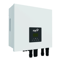
• Trim the wires:
- Trim all the wires to 52.5mm and the PE wire to 55mm.
- Use the crimping pliers to trim 12mm of insulation from all wire ends as below.
Note: Please refer to local cable type and color for actual installation.
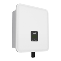
A. EPS Wiring
• Separate the EPS plug into three parts as below.
- Hold middle part of the female insert, rotate the back shell to loosen it, detach it from female inset.
- Remove the cable nut (with rubber insert) from the back shell.
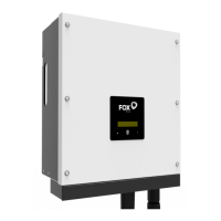
• Slide the cable nut and then the back shell onto the cable. Install the cable into the plug terminal and
lock the screw, torque is (1.0+/-0.2 N.m).
• Push the threaded sleeve into the socket, tighten up the cap on the terminal.
•
L: Brown/Red Wire
N: Blue/Black Wire
PE: Yellow & Green Wire