21
6.5 Electrical Connection
A. Communication Device Installation (Optional)
KH/KA series inverters are available with multiple communication options such as WiFi, LAN, 4G, RS485
and Meter with an external device.
Operating information like output voltage, current, frequency, fault information, etc., can be monitored
locally or remotely via these interfaces.
• WiFi/LAN (Optional)/4G (Optional)
The inverter has an interface for WiFi/LAN/4G devices that allow this device to collect information from
inverter; including inverter working status, performance etc., and update that information to monitoring
platform (the WiFi/LAN/4G device is available to purchase from your local supplier).
Connection steps:
1. Plug the WiFi/LAN/4G device into “WiFi/LAN/4G” port at the bottom of the inverter.
2. For WiFi device: Connect the WiFi with the local router, and complete the WiFi configuration (please
refer to the WiFi product manual for more details).
3. Set-up the site account on the Fox ESS monitoring platform (please refer to the monitoring user
manual for more details).
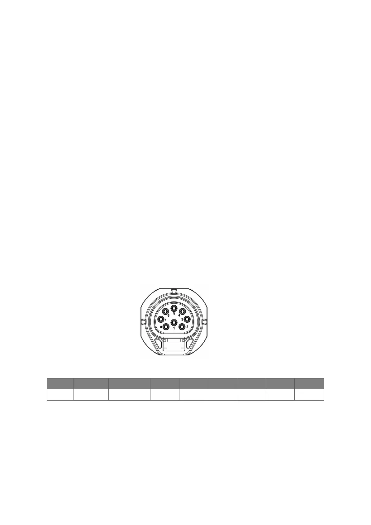
• Meter/CT/RS485
The inverter has integrated export limitation functionality. To use this function, a power meter or a
CT must be installed. The PIN definitions of Meter/CT/485 interface are as below.
Note:
• CT1: For KH/KA.
CT2: Grid tied inverter (if have).
• Compatible Meter type: DDSU666 (CHINT), SDM230 (EASTRON).
• CT