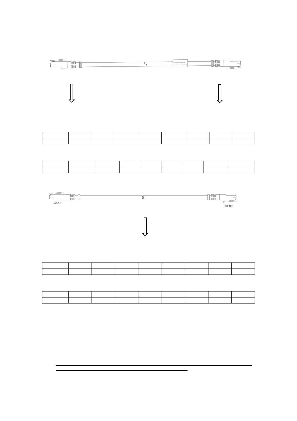
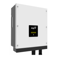
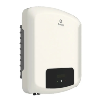
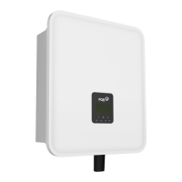
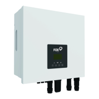
L :To match the different inverters, our accessory packs are differentiated, so please look at the wire
markings on the white sleeves before wiring.
L-1
Please plug into the RS485
port of the inverter.
RS485 (Inverter side) Pin definition:
RS485 (Battery side) Pin definition:
L-2
One end is plugged into the inverter CAN port, the other end into the battery CAN port.
CAN (Inverter side) Pin definition:
CAN (Battery side) Pin definition:
Note:
1. Use only the parts included with the battery pack to ensure proper installation. If anything is
damaged or missing, please contact your distributor.
2. Package 1 is provided separately, not including in battery package. Please contact your distributor if
you do not have it. Also you will receive L-1 or L-2 in package 1 .
3. Select an interface (CAN/RS485) based on the actual inverter interface type.
4. If the definition of the communication port from your inverter to the battery is different from
all of the above, please make your own communication cable.
Please plug into the
battery RS485 port.



 To Next Page