21
• Communication and Monitoring
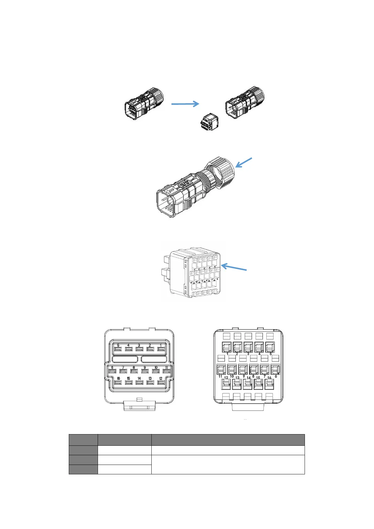
This series of inverters provide an optional 16 Pin communication port.
Installation steps are as below:
Take out the rubber core:
Screw out the sealing cap and route a communication wire through a tail portion of the terminal:
Plug the communication wire into the rubber core:
The wire sequence of the rubber core is shown as below:
The specification of a
communication wire is
0.35~0.75mm².
Plug the communication
wire.



 To Next Page