•
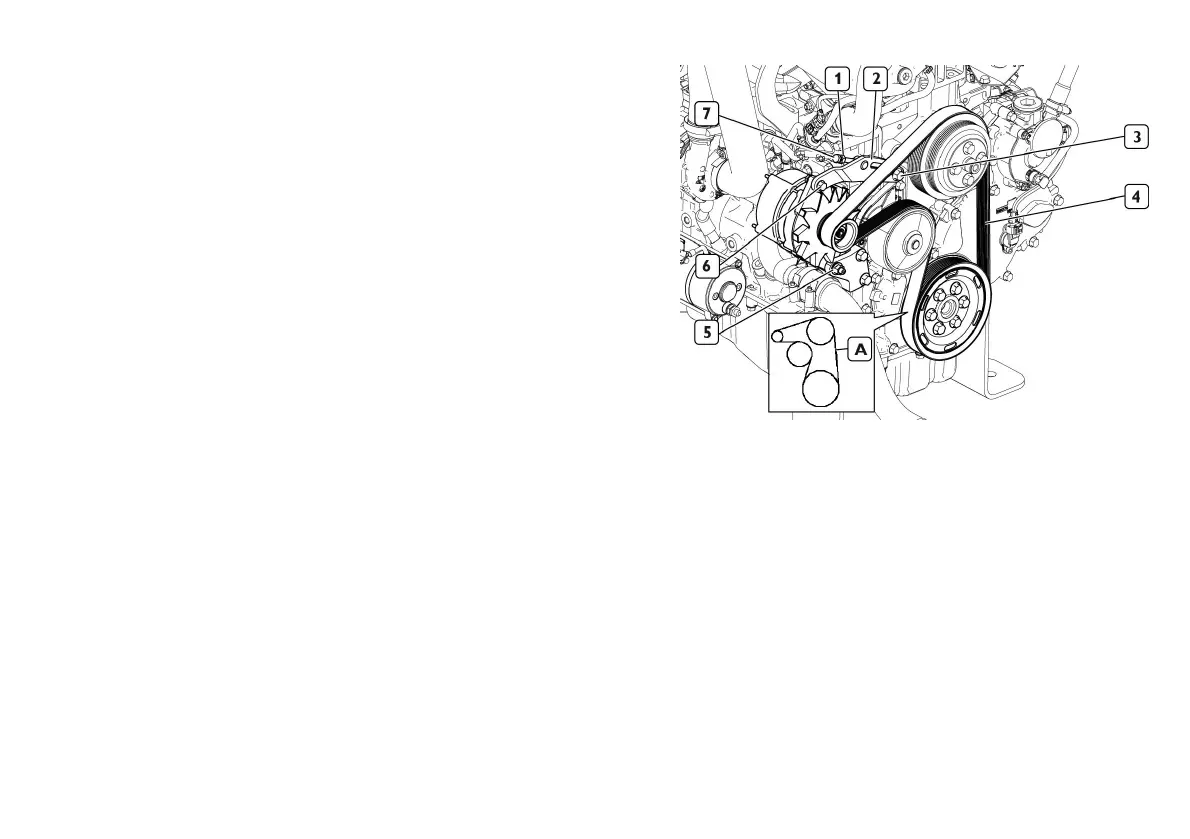
Usethedesignatedtooltocheckthetensionoftheauxiliaryunitdrive
belt.Thecorrectstatictensionoftheauxiliaryunitdrivebelt(4) (4)
(4)
must
fallwithintherangeindicatedbelow:
•
Staticvoltage(Valuemeasured(N/rib/spam)/Controlfrequency(Hz)
@23 23
23
+ +
+
/ /
/
- -
-
5 5
5
°C °C
°C
)
Minimum(57/100)
Nominal(75/115)
Maximum(93/132)
•
Ifnecessary,regulatethetensionofthebelt(4) (4)
(4)
asdescribedbelow.
•
Loosenthebolt(5) (5)
(5)
anchoringthealternatortoitslowermountand
thescrew(3) (3)
(3)
fasteningthetensioningbrackettothecrankcase.
•
Proceedwithtensioningtheauxiliarydrivebelt(4) (4)
(4)
bytighteningthe
adjustmentscrew(7) (7)
(7)
untilthetensioningbracket(2) (2)
(2)
reachesthepo-
sitionofmaximumadjustmentextensionavailable,asshowninthe
gure
•
Fullyrotatethecrankshafttwicetoensurethattheancillarydrivebelt
(4) (4)
(4)
hassettled.
•
Tightenthescrew(3) (3)
(3)
fasteningthetensioningbracket(2) (2)
(2)
tothe
crankcasetoatorqueof50 50
50
N·m N·m
N·m
±5
•
Tightenthebolt(5) (5)
(5)
anchoringthealternatortoitslowermounttoa
torqueof50 50
50
N·m N·m
N·m
±5.
•
Turntheadjustmentscrew(7) (7)
(7)
twofullturnsanti-clockwise,then
tightentherelativelockingnut(1) (1)
(1)
toatorqueof30 30
30
N·m N·m
N·m
±3
NOTE: NOTE:
NOTE:
The static tension of the belt is measured in the intermediate point (A) (A)
(A)
of the branch between the crankshaft pulley and the fan drive pulley.
•
Fittheprotectivegrillecorrectlyinsertingtheanti-vibrationplugs.
Screwinthefasteningscrews.
38