13
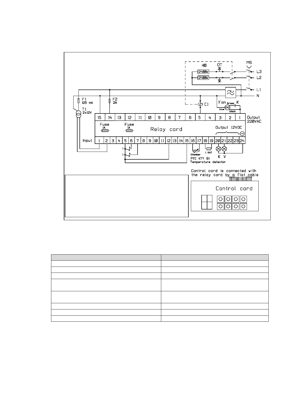
7.3 Circuit diagram
Output Input
1. Ventilator power 1 5. Common for all incoming
5. Heating contactor 6. Front door
20. Yellow in operation indicator by clean side
(pass-through model)
7. Back door (pass-through model)
21. Green cycle completed indicator by clean
side (pass-through model)
15. Pass-through model identifier
24. 12VDC minus terminal 16. Thermal sensor in chamber
17. Thermal sensor in chamber
Phase advance
Heating elements
MS
Main switch 2x2400 W
T1
Transformer 12 V
C1
Contactor
Fan
Ventilator
F1
Fuse 125 mA (T)
K
Capacitor 6µF,400V
F2
Fuse 2A (F)
OT
Overheating protector