INSTALLATION AND SETUP
Programming: Advanced Setup > Motor Protection > Current
19
Programming: Advanced Setup > Motor Protection > Current
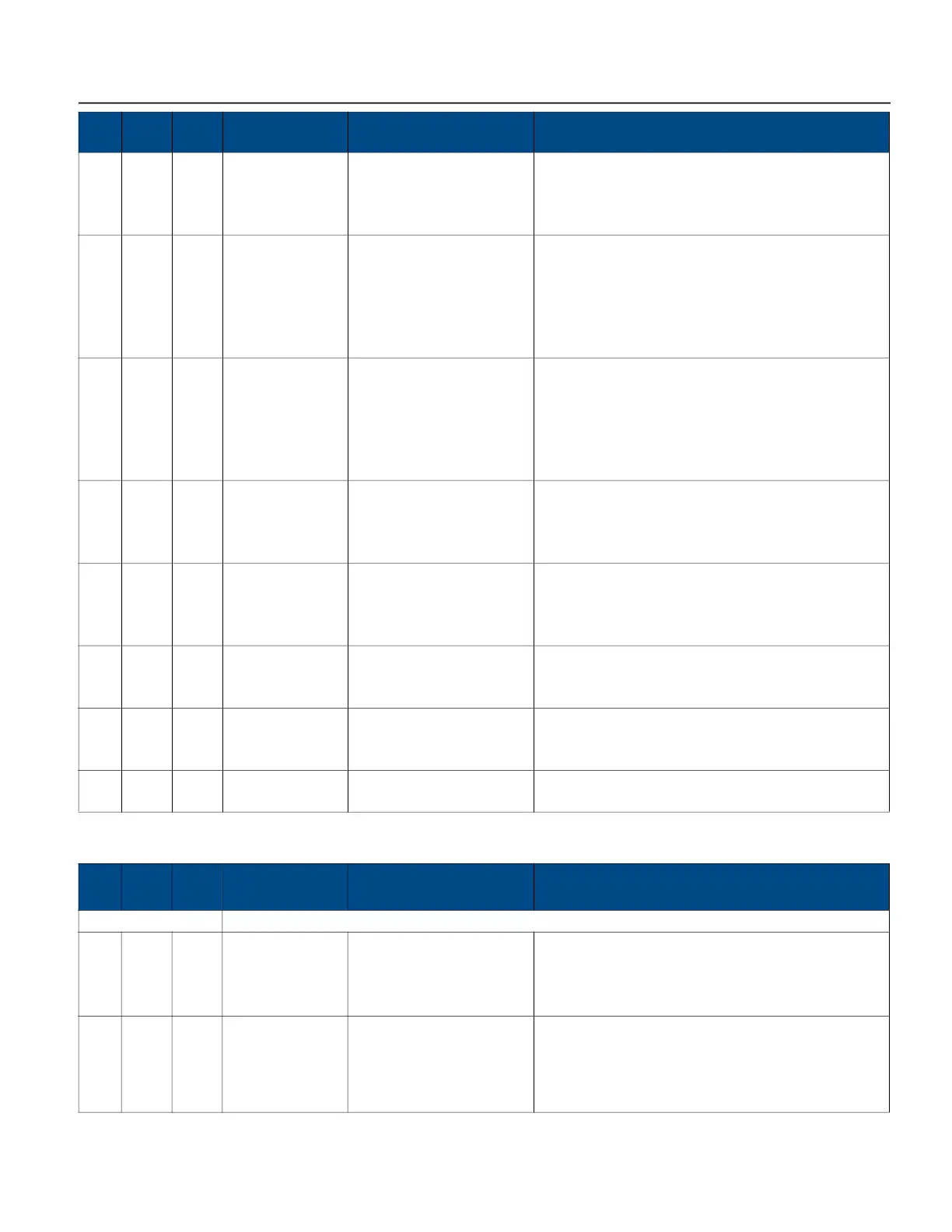
433 RW N Overvoltage
(level)
101 to 125; 110 (default) This sets the percentage of nominal voltage that triggers
a fault when over voltage trip level is reached. For
example, setting a value of 110 means 110% of the nominal
voltage value will trigger a fault.
452 RW N Underpower
(enable)
0 - Off
1 - Fault and Alarm (default)
2 - Alarm Only
When set to Alarm Only or Fault and Alarm, this trips if
the measured kW is less than the kW trip point setting
(next menu item) continuously for a time that exceeds
the under power trip time setting. The trip time is set in
Advanced Setup > Motor Protection > Voltage >
Undervoltage > Time to Trip.
453 RW N Underpower
(level)
1 to 99;
SMS default = 65
Reduced Voltage SMS
default = 50
This sets the percentage of the calculated nominal power
level that triggers a fault when the trip level is reached.
For example, setting a value of 110 means 110% of the
nominal power value will trigger a fault. As the
percentage changes, the wattage setting is automatically
calculated.
418 RW N Current Unbalance
(enable)
0 - Off
1 - Fault and Alarm (default)
2 - Alarm Only
When set to Alarm Only or Fault and Alarm, an alarm
triggers if the calculated average of the three line-to-line
currents exceed the user set nominal Current Unbalance
percentage (next menu item).
419 RW N Current Unbalance
(level)
1% to 50%; 5% (default) Trips if any of the 3 measured phase currents deviate from
the average current by a value greater than or equal to
the trip percentage setting. For example, setting a value
of 5 means 5% of current unbalance.
106
107
W
W
Y
Y
Date MM/DD/YY Sets the system date. Only the 3 least significant bytes
are used. From least to most significant byte: year, day,
month (0x00MMDDYY).
108
109
W
W
Y
Y
Time HH:MM:SS Sets the system time. Only the 3 least significant bytes
are used. From least to most significant byte: second,
hour, day (0x00HHMMSS).
N/A RW N Name Tag 16 characters maximum The name tag identifies this SubMonitor Connect when
using communication protocols.
Mod
bus
RW RC
Menu / Parameter
Name
Range Description
Mod
bus
RW RC
Menu / Parameter
Name
Range Description
Overload Menu
FLA/SFA Motor 1.0 A to 1000.0 A For surface motor applications, this should be set to the
FLA listed on the motor nameplate.
For submersible motor applications, set according to the
SFA listed in the Franklin AIM manual.
403 RW N Trip Class 5
10
20
30
S - Submersible Motor
Sets the overload trip class. This follows the industry
standard I
2
t trip curve.
Surface Pump default = 10
Submersible Pump default = S
 Loading...