INSTALLATION AND SETUP
Start-Up Programming
15
5. Connect each CT wire to it’s other CT wire via the grounded terminal block (inset photo on previous
page).
CT Kits available:
• 5860015170 - SubMonitor Connect CT Kit, 120-270A
• 5860015180 - SubMonitor Connect CT Kit, 200-400A
• 5860015210 - SubMonitor Connect CT Kit, 320-720A
• 5860015190 - SubMonitor Connect CT Kit, 400-900A
When using CTs as part of the SubMonitor Connect system, be sure to program the SubMonitor Connect
appropriately. Refer to “
Programming: Advanced Setup > Administration” on page 26 for External CT Ratio
setup, or make this setting using the FE Connect mobile app.
An example for CT use:
An installation is using 500:5 ratio CTs with 500 A on the power lines.
The SubMonitor Connect measures 5 A. The SubMonitor Connect resolution is 0.1 A, which equates to ±10 A
reading on the motor power lines. This means that the SubMonitor Connect reading difference can be
between 505 A and 495 A.
Refer to “
Wiring Diagrams for Panels” on page 59 for schematics.
Start-Up Programming
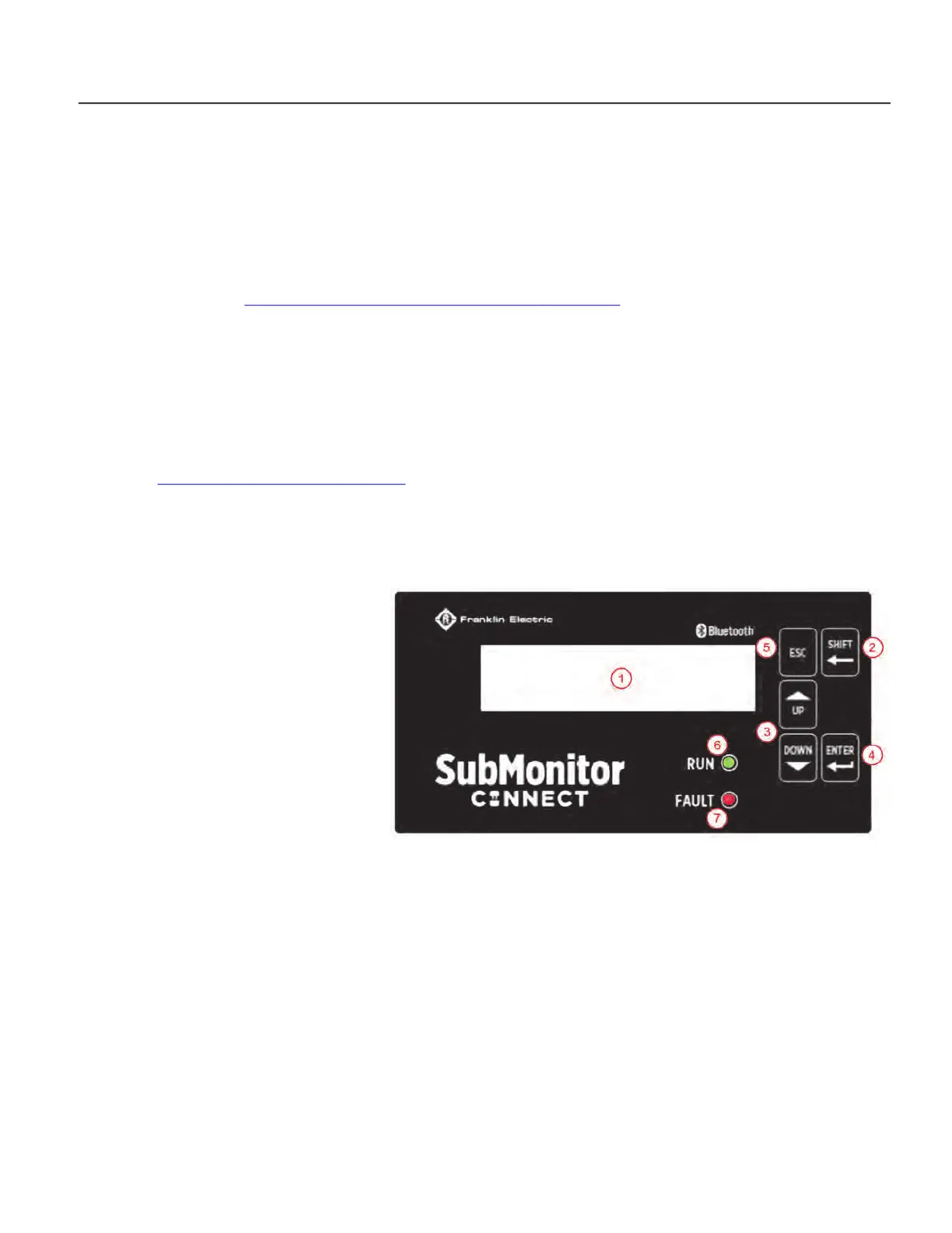
Using the Control Interface
1. Display: Shows system status information
and programming menu items.
2. SHIFT: Press SHIFT to move the blinking
cursor left one position for each button
press. When the cursor reaches the left-
most editable position, another SHIFT
button press moves the cursor to the
right-most position of the parameter.
3. UP and DOWN: Use to navigate menus
and adjust parameters.
4. ENTER: Executes menu selection and con-
firms any changes made to parameter
settings. Also allows user to access sub-
menus and selected parameters.
5. ESC: Pressing the ESC button moves the menu back one level.
6. Run LED: This green LED lights to alert the user to water flow (the pump motor is running).
7. Fault LED: Off (when not lighted) indicates normal operation. A blinking LED indicates the measured
current is higher than the Overload setting, and will trip soon if the condition persists. A solid on LED
indicates an active fault condition.
Remove the detachable display for access to these items:
TEST/RESET: Pressing this button resets a fault condition, if present. In a non-fault condition, pressing
this button puts the SubMonitor Connect into a fault state.
 Loading...