EasyManua.ls Logo

Franklin PUMPTEC-PLUS - User Manual

Franklin PUMPTEC-PLUS
48 pages
Print Icon
To Next Page IconTo Next Page
Loading...
PUMPTEC-PLUS
Pump Protection System
Installation and Operating Guide

Questions and Answers

  • B
    Benjamin CallahanJul 27, 2025
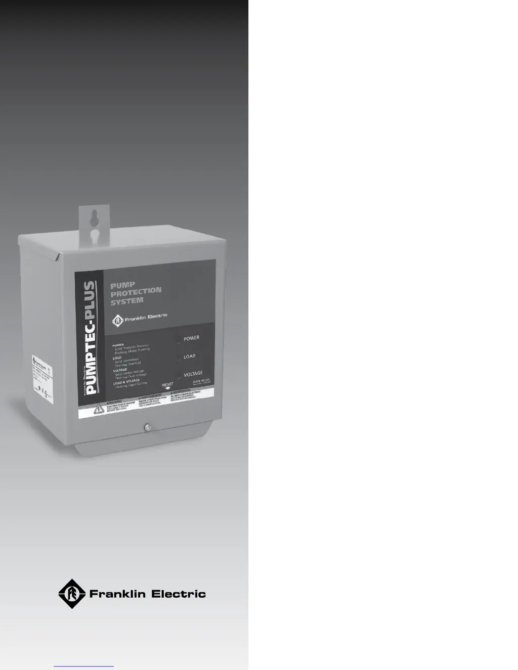
    What to do if the Franklin PUMPTEC-PLUS has a solid red light?
    • S
      Scott HahnJul 27, 2025
      If the Franklin Protection Device shows a solid red light, it indicates that the line voltage is below 207 Volts. You should check the line voltage. Also, inspect for loose connections, as these can cause voltage drops. If you're using a generator, be aware that a loaded generator can cause the line voltage to drop too low. If the generator voltage remains below 207 Volts for more than 2.5 seconds, the Protection Device will trip. This can also occur if the line frequency rises too far above 60 Hz.
  • M
    Matthew KennedyJul 31, 2025
    How to troubleshoot a Franklin PUMPTEC-PLUS that appears dead (no lights)?
    • M
      Michael PetersJul 31, 2025
      If the Franklin Protection Device unit appears dead with no lights, the cause may be no power to the unit. Check the wiring to ensure the power supply voltage is correctly applied to the L1 and L2 terminals of the Pumptec-Plus. Also, if a pressure switch or another control device is wired to the input, ensure that this switch is closed.
  • H
    horncharlesAug 6, 2025
    Why is my Franklin PUMPTEC-PLUS showing a flashing yellow light?
    • M
      Mr. Phillip KnappAug 6, 2025
      If the Franklin Protection Device shows a flashing yellow light, it means the unit needs to be calibrated. The Pumptec-Plus is calibrated at the factory, so it will overload on most pump systems when first installed. This is a reminder that calibration is required before use. Refer to step 7 of the installation instructions. Also, the Pumptec-Plus should be calibrated on a fully recovered well with maximum water flow. Flow restrictors are not recommended.
  • M
    Michelle JohnsonAug 11, 2025
    What does it mean when my Franklin PUMPTEC-PLUS Protection Device is flashing red and yellow lights?
    • W
      wandalongAug 11, 2025
      If the Franklin Protection Device shows flashing red and yellow lights, it could be due to a power interruptor. During installation, if power is cycled more than four times within a minute, the Pumptec-Plus will trip on rapid cycle. To resolve this, press and release the reset button to restart the unit. Another cause could be a bobbing float switch, which may cause the unit to detect a rapid cycle condition on any motor or an overload condition on two-wire motors. Try to reduce water splashing or use a different switch.
  • M
    melissaschultzAug 16, 2025
    Why is my Franklin PUMPTEC-PLUS flashing a red light?
    • E
      elliottstephanieAug 16, 2025
      If the Franklin Protection Device shows a flashing red light, it indicates that the line voltage is over 253 Volts. Check the line voltage. If you are using a generator, the line voltage may become too high when the generator unloads. The Pumptec-Plus will not allow the motor to turn on again until the line voltage returns to normal. Over voltage trips will also occur if the line frequency drops too far below 60 Hz.
  • R
    Rachel AllenAug 21, 2025
    What to do if the Franklin Protection Device has a flashing yellow light during calibration?
    • M
      Michael MitchellAug 21, 2025
      Step C of the Franklin Protection Device calibration instructions indicates that a flashing green light condition will occur 2 to 3 seconds after taking the snapshot of the motor load. On some two- wire motors, the yellow light will flash instead of the green light. Press and release the reset button. The green should start flashing.

Summary

Before Getting Started

Safety Alerts and Hazard Definitions

Explains safety symbols and defines hazard levels like DANGER, WARNING, CAUTION, and NOTICE.

Product Features and Specifications

Installation Information Overview

Introduces key installation considerations and notes before proceeding.

Installation Procedures

Cover Removal

Instructions for safely removing the protective cover of the unit.

Timer Switch Setting

Guidance on setting the automatic timer for motor restart intervals.

Mounting and Wiring Connections

Unit Mounting

Steps and considerations for securely mounting the Pumptec-Plus unit.

2-Wire Installation Wiring

Diagram and instructions for connecting the unit in a 2-wire motor configuration.

Wiring Configurations and Power Up

3-Wire Installation Wiring

Diagrams and instructions for 3-wire motor configurations.

Cover Replacement

Procedure for reattaching the unit's cover after installation.

Applying Power

Steps for safely applying electrical power to the installed unit.

Calibration and Basic Operation

Calibration Process

Detailed steps to calibrate the Pumptec-Plus for optimal pump protection.

Operation Principles

Explanation of the unit's operation and indicator light functions.

Indicator Light Functions

Green Light Interpretation

Meaning of the green indicator light regarding system power and motor status.

Yellow Light Interpretation

Meaning of the yellow indicator light for load-related faults.

Fault Lights and Reset Mechanism

Red Light Interpretation

Meaning of the red indicator light for voltage faults.

Combined Fault Lights

Interpreting combinations of flashing red and yellow lights.

Reset Button Operation

How to use the reset button for clearing faults and initiating calibration.

Troubleshooting During Installation

Troubleshooting After Installation

Standard Limited Warranty

Franklin PUMPTEC-PLUS Specifications

General IconGeneral
BrandFranklin
ModelPUMPTEC-PLUS
CategoryProtection Device
LanguageEnglish