Do you have a question about the FRC InControl TGA300 and is the answer not in the manual?
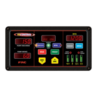
Overview of the all-in-one pressure governor and instrument panel using microprocessor technology.
Lists key features of the pressure governor and instrument panel, including J1939 CAN bus and programmable presets.
Details specifications for the control module, including power, current, dimensions, and unit of measure.
Lists parameters displayed by LED bar graphs, such as engine oil pressure and battery voltage.
Provides specifications for the discharge and intake pressure sensors, including model, range, and voltage.
Lists engine types compatible with the pressure governor, including Cummins, Detroit Diesel, and Caterpillar.
Lists the components of the INControl pressure governor and instrument panel, including control module and sensors.
Details buttons and knobs for operating the governor and setting parameters.
Describes LEDs for system status, engine warnings, and alarm suppression.
Provides step-by-step instructions for mounting the control module and its dimensions.
Instructions for mounting and connecting discharge and intake pressure sensors.
Details installation of buzzer, high-idle kit, and remote governor option.
Explains how to use the INC/DEC buttons and control knob for settings.
Lists error codes, their message display, and probable causes.
Lists fault warning codes, descriptions, and factory default settings.
Details pressure mode, max RPM, and low pressure settings.
Explains valve control and operating from a pressurized source.
Details governor response to 'Running Away From Water', 'Low Water', and 'No Supply Water'.
Explains RPM mode, pressure limits, and control usage for RPM settings.
Describes how to switch between Pressure and RPM modes based on engine state.
Details the programming code P221 for setting the maximum RPM limit.
Explains the remote governor's functions and programming requirements.
Explains how to view detailed operating data like engine hours and temperatures via the MENU button.
Details how to activate the high-idle function and its factory setting.
Procedure for changing pre-programmed pressure or RPM settings.
Lists program functions like revision number, date, time, and fault codes.
Step-by-step guide to accessing and navigating program codes and settings.
Details the password code 1111 for accessing calibration programs.
Details the password code 1221 for changing limited program functions.
Instructions for entering the calibration password code 1111.
Provides a quick reference for calibration codes C1, C2, and C3.
Procedure for self-calibrating discharge and intake pressure sensors.
Procedure for calibrating engine RPM using a reference tachometer.
Details the 12-pin connector pinout and basic wiring for the governor.
Details the 8-pin connector pinout and its wiring connections.
Wiring details for connecting the secondary controller.
Wiring diagram and pinout for the 3-pin pressure sensor cable.
Diagram and pinout for the typical 9-pin Deutsch diagnostic connector.
Details J1939 databus interface for Cummins engines, including calibration notes.
Details J1939 databus interface for Detroit Diesel engines, including DDEC versions.
Wiring for J1939 CAN bus control on Navistar 12VXY engines.
Wiring for engine control output via Body Builder J1939 Datalink.
Details PTO configuration and J1939 Speed Command for Caterpillar engines.
Details J1939 translator module, ODB-II connection, and SEIC interface for Ford vehicles.
Instructions for installing the J1939 translator module and harnesses.
Wiring diagrams for Stationary and Split Shaft Mode SEIC on Ford engines.
Shows J1939 CAN bus control wiring for V-MACK IV engines.
Details BWS connector and shows J1939 CAN and RPM control wiring for Scania Type A.
Details BCI module and C493 connector, showing J1939 CAN wiring for Scania Type D.
Wiring for Mercedes DDEC VI and older engines, including J1939 CAN and throttle override.
Details 6-pin optional connector inputs and wiring for ACTROS models.
Shows J1939 CAN bus control wiring for John Deere PowerTech engines.
Details J1939 CAN bus control wiring for MAN engines.
Wiring for CAN bus control on IVECO vehicles using EM and CANopen.
Explains high-idle activation and provides a wiring schematic with diodes.
Explains the use of flyback diodes with inductive loads and provides circuit examples.
| Communication | CAN, USB |
|---|---|
| Output Voltage | 5V DC |
| Operating Temperature | 70°C |
| Protection | Overvoltage, Overcurrent |
| Certification | RoHS |