TGA300 Rev180405
28
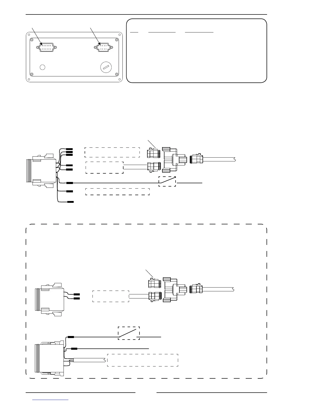
Figure 5. TGA 8-Pin Connector Wiring
8-Pin Connector/Cable
Pin Wire Color Description
1 Red +5 VDC Reference From ECM
2 Black ECM Ground
3 Orange Engine Control Signal To ECM
4 White High-Idle Active Input (+12 VDC)
5 Yellow FRC Datalink (+)
6 Green FRC Datalink (–)
7 Blue Buzzer Ground (300 mA max)
8 Brown Throttle Enable Signal Output
Note: Not all wires are used for all engines. Refer to the engine
specic wiring diagram for interface connections.
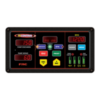
Rear View
12 and 8 Pin Connectors
Top
USB
Access Port*
Pin 1
Pin 1
Vent
Note: An optional 6-pin connector is installed
when external sensors are required.
BLU
YEL
GRN
To Ground Side of Buzzer
To Engine Control
(See Engine Specic Wiring)
WHT
High-Idle
Switch
Refer to High-Idle
Wiring for details.
RED
BLK
ORN
BRN
FRC Datalink (+)
FRC Datalink (–)
8-Pin
Connector
To the Secondary
Controller
Data Bus
Terminator
Note: The program code P303 must be set to REMOTE on the Secondary Controller control module.
Secondary Controller
12 and 8 Pin Connector Wiring
+12 VDC
GND
Ignition Key
RED
BLK
To J1939
(See Engine Specic Wiring)
12-Pin
Connector
NOTE: Terminating resistor
and adapters are included in the
kit for connection to the primary
display; no other wires are
required for remote operation.
8-Pin
Connector
YEL
GRN
FRC Datalink (+)
FRC Datalink (–)
To the Primary
Controller
Data Bus
Terminator
Secondary Controller, Cables and Connections
*NOTE: If opened, USB access port plug
must be tightened to a torque of 8-10 in-lbs.
Exceeding this torque value can result in
damage to its water seal capability.
Warning: Flange may not fully bottom out.
 Loading...