PBA100 Rev0305PreLim
3
PRELIMINARY DOCUMENT
FOR REFERENCE/REVIEW ONLY
List of Tables
Table 1. Pressure Sensor Output Voltage .................................................................. 5
Table 2. Error Codes ............................................................................................... 15
Table 3. Fault Warning Codes.................................................................................. 15
List of Figures
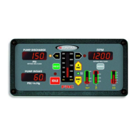
Figure 1. Controls and Indicators .............................................................................. 9
Figure 2. Control Module Mounting Dimensions .................................................... 11
Figure 3. Pressure Sensor ........................................................................................ 12
Figure 4. Pressure Transducer Wiring...................................................................... 20
Figure 5. Common OEM 9-Pin Diagnostic Connector............................................ 21
Figure 6. 12-Pin Connector Wiring .......................................................................... 22
Figure 7. 8-Pin Connector Wiring ............................................................................ 23
Figure 8. Cummins PBA101 Wiring......................................................................... 24
Figure 9. Detroit Diesel PBA102 Wiring ................................................................... 25
Figure 10. Navistar PBA104 Wiring.......................................................................... 26
Figure 11. Caterpillar PBA105 Wiring...................................................................... 27
Figure 12. Mercedes PBA110 Wiring ...................................................................... 28

 Loading...