6
7. Operating procedures
CHECK THAT :
* The motor rating is compatible with the drive rating
* The motor winding connection is compatible with the drive output voltage
(refer to chapter 5; section 1.3.)
* AC input power circuit breaker of the correct rating is installed upstream on the low voltage
switch - board (refer to chapter 5, section 1.2.)
* the drive is firmly attached in an upright position and is properly ventilated
7.1. Procedure I - remote (external) control, without using MINITERMINAL (control pod)
and TELECONTROL (remote control unit)
• connect the control cable to terminal board (shown in FIG 2)
• put the AC input power circuit breaker in "ON" position - the red "POWER" light goes on.
In the event of a fault, the red "FAILURE" light goes on.
7.1.1. Speed control
• potentiometer : terminals 8, 9, 11
or
• voltage signal : terminals 9, 11
or
• current signal : terminals 10, 11
7.1.2. "Run/stop"
• connect 24 V DC to the terminal 3 (control switch or PLC output) :
The motor will start and run up to the set speed.
Acceleration is set by parameter "ACC" (refer to chapter 9.; section 1.)
• disconnect 24 V DC from the terminal 3 :
The motor will ramp or coast to a stop.
Deceleration is set by parameter "DEC", stopping mode is set by parameter " CSTP "
(refer to chapter 9; section 1. and user manual for the MINITERMINAL - control pod)
7.1.3. " Fwd/rev" - Forward/reverse
• connect 24 V DC to the terminals 4 and 3 simultaneously (control switch or PLC output) :
Running motor - motor will ramp by set decel time to a stop and then will run up by set accel time
in a reverse direction to the required speed
Motor is stopped - motor will start and run up by set accel time in a reverse direction to the
required speed
• disconnect 24 V DC from the terminal 4 (24V DC is connected to the terminal 3) :
The motor will ramp to a stop and then will run up in a forward direction to the set speed.
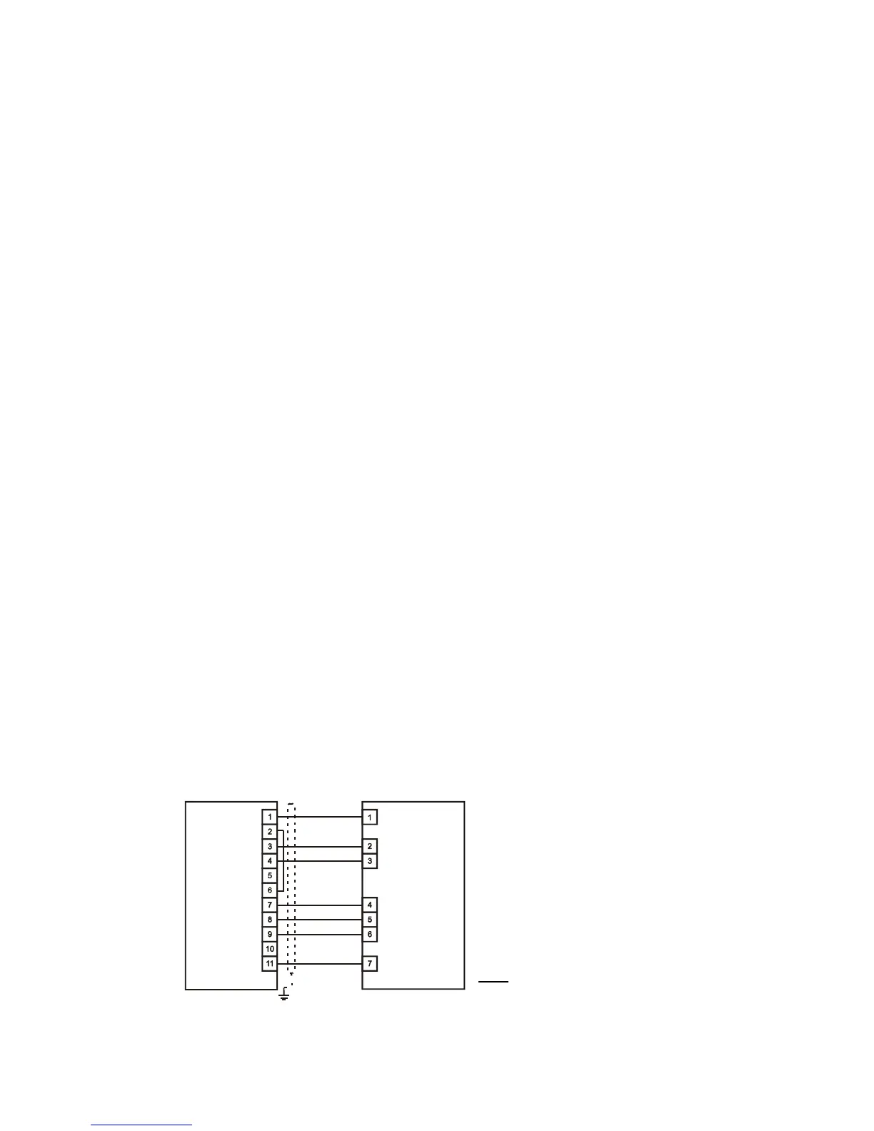
7.2. Procedure II - remote (external) control, using TELECONTROL - remote control unit (option)
• connect the control cable to the terminal boards at the drive and the TELECONTROL (shown in FIG
3)
FIG 3
• put the AC input power circuit breaker in "on" position - the red "Power" light goes on.
In the event of a fault; the red "FAILURE" light goes on.
F
R
E
C
O
N
T
E
L
E
C
O
N
T
R
O
L
/
F
I
A
F
R
E
C
O
N
F
I
A
-
L