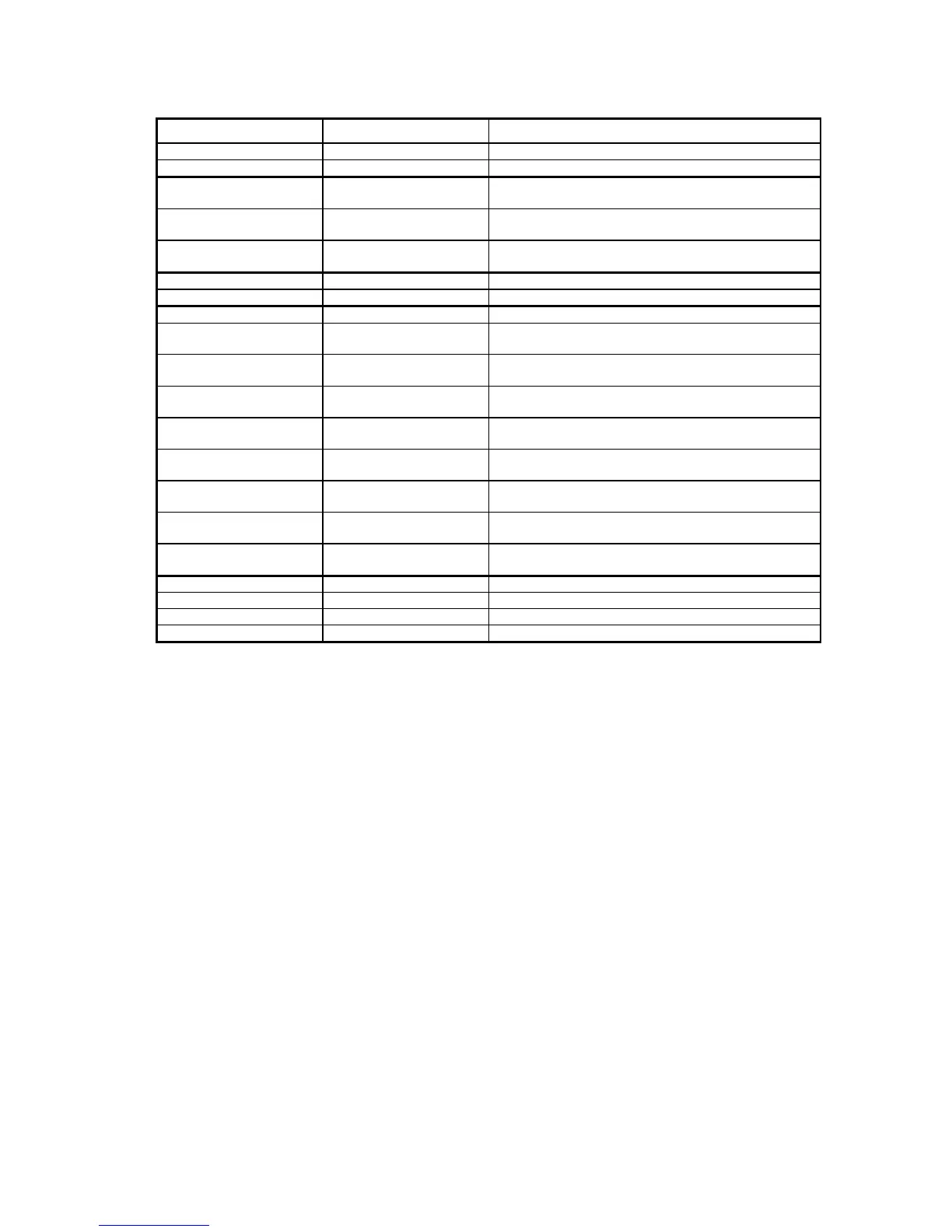
(Hz) required output frequency
F0 0 - 125 Hz required output frequency
(0% analogue input signal)
F100 0 - 125 Hz required output frequency
(100% analogue input signal)
FERR 0 -125 Hz required output frequency
(analogue input signal non-present)
ACC 0,5 - 500 Hz/s FOUT acceleration
DEC 0,5 - 500 Hz/s FOUT deceleration
FBAS 25 - 241 Hz base frequency
U0 0 - 22% V
MAX
output voltage
(FOUT = 0 Hz)
U1 1 - 30% V
MAX
output voltage
(FOUT = 1/8 FBAS)
U2 2 - 40% V
MAX
output voltage
(FOUT = 2/8 FBAS)
U3 4 - 50% V
MAX
output voltage
(FOUT = 3/8 FBAS)
U4 6 - 60% V
MAX
output voltage
(FOUT = 4/8 FBAS)
U5 10 - 70% V
MAX
output voltage
(FOUT = 5/8 FBAS)
U6 16 - 81% V
MAX
output voltage
(FOUT = 6/8 FBAS)
U7 32 - 93% V
MAX
output voltage
(FOUT = 7/8 FBAS)
CINP 0, 1, 2, 3 reference input selection
CSTP 0,1 stopping mode selection
CRTR 0,1 reset mode selection
SET support parameter for user set programming
For more information: refer to user manual for the MINITERMINAL.
9.2. FRECON TELECONTROL - remote control unit
• Functions:
- fault LED indication
- speed control : potentiometer
- run/stop : change-over switch
- forward/reverse : change-over switch
• Dimensions : 110 x 80 x 55 mm (h x w x d)
• Mounting: externally anywhere convenient at a distance permitted by a maximum cable length of
50m from the drive to the TELECONTROL.
9.3. Braking unit
A decelerating AC motor regenerates energy into the inverter drive. This energy can only be dissipated
within the drive, it cannot be returned to the AC supply by the FRECON unit. If the regenerated power
is less than approx. 4% of rated drive power, the braking unit is not necessary to use.
Connection: terminals -B, +B (FIG. 1)