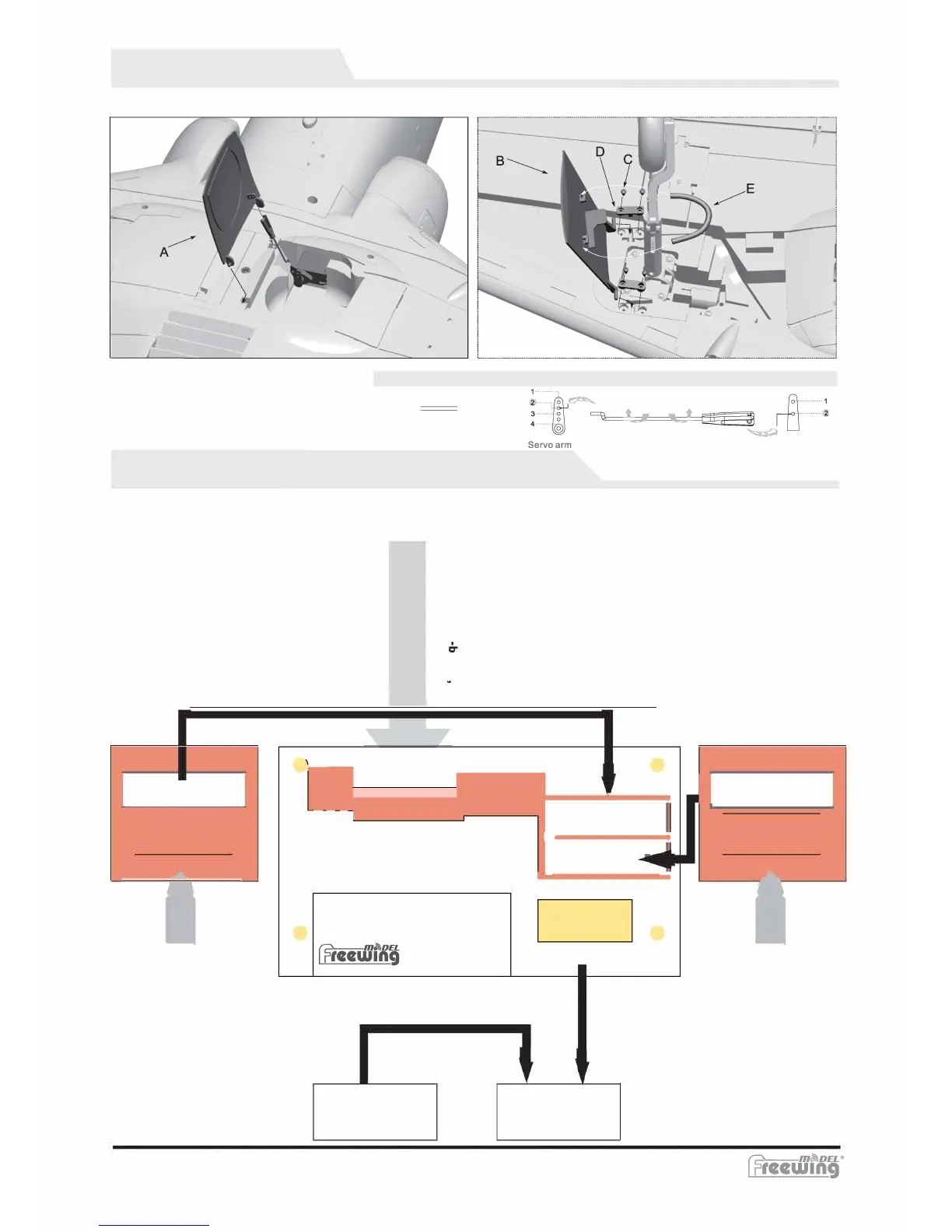
Main Gear Door Assembly
Refer to the following photos for assembling and disassembling main gear doors.
I
)
Servo pushrod installation hole
(1.29 in)
Integrated Circuit Module Connection Diagram
The integrated circuit module has two functions:
1.
To control the LED lights, landing gear and
gear doors.
2.
To connect multiple servos conveniently.
=
-
.
Connect to the integrated circuit module (E04) using the wing connection cables.
L
C V
lo
1°
, t
0
0
i I �
======="
lane E
Integrated circuit module
0
0
0
>
>
� !
EN
u
-
.
I: :
•••••
L
ESC signal cable, connects
directly to the receiver.
lntegrated circuit module output.
Refer to the assigned channel names and
use the connection cables to insert the
correct output to the corresponding input on
the receiver .
T-45 Goshawk
ESC
-9-
Receiver
A. Main gear door L
B. Main gear door R
C. Screws (PT2.3x6mm)
D. Plastic retainer
E. Spring
Rear cabin door pushrod size