transparent drain hose connected to a catch
bottle. The hose needs to fit the bleed valve tight
enough so it does not fall off when fluid is
pumped out.
NOTE: The following steps require two people –
one in the cab to work the clutch pedal, and one
to open and close the bleed valve and watch
the fluid.
4. Bleed the system, as follows.
4.1 Open the bleed valve.
4.2 Depress the clutch pedal until it stops.
4.3 Close the bleed valve.
4.4 Return the pedal to the upper position.
4.5 Repeat the previous steps until the fluid is
clear and free of air bubbles.
4.6 Depress the clutch pedal. There should
be resistance over the full pedal stroke.
5. Check the fluid level in the reservoir. If neces-
sary, add or drain fluid to bring the fluid level to
between the MIN and MAX lines marked on the
side of the reservoir. Install the reservoir lid.
6. Disconnect the transparent hose. Tighten the
bleed valve 88 lbf·in (1000 N·cm) and install the
cap on the slave cylinder bleed valve.
25–05 Clutch Adjustment,
Manually Adjusted
Clutches
NOTE: This procedure is only required for ve-
hicles equipped with non-synchronized transmis-
sions and manually adjusted clutches.
Release bearing travel is the clearance between the
rear surface of the release bearing housing and the
forward surface of the clutch brake disc. This dis-
tance must be maintained between 1/2 and 9/16 inch
(12.7 and 14.3 mm).
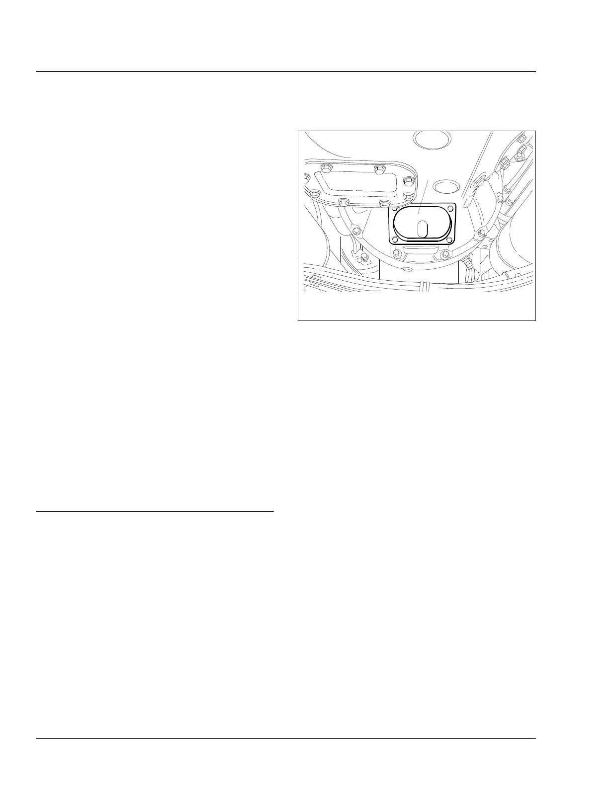
1. Remove the clutch inspection cover from the bell
housing. See
Fig. 6.
2. Slide the clutch brake tight against the transmis-
sion input-shaft bearing cap.
IMPORTANT: Release bearing travel tool A02-
12419-000 is available through the PDCs. The
fork at one end of the tool has green tape on it,
and has two 0.50-inch (12.7-mm) diameter tips;
the fork at the other end has blue tape on it,
and has 0.56-inch (14.3-mm) diameter tips. See
Fig. 7.
3. Measure the release bearing travel. See Fig. 8
for the correct dimension to measure. Using both
ends of the release bearing travel tool, check this
gap as follows:
Position the tool so that the legs of the fork at
the blue 0.56-inch (14.3-mm) end straddle the
transmission input shaft. If the tool fits loosely,
the gap is too wide and adjustment is needed.
Go to the next step.
If the blue 0.56-inch (14.3-mm) end can’t be in-
serted in the gap, then try to insert the green
0.50-inch (12.7-mm) end.
If the green end of the tool can’t be inserted in
the gap, adjustment is needed. Go to the next
step.
If the green end of the tool fits — snugly or
loosely — then no adjustment is needed. Nothing
more needs to be done. Install the clutch inspec-
tion cover.
4. Release the clutch by depressing the pedal.
Block the pedal in the released position, or have
someone assist you by holding the pedal down
during the adjustment procedure.
f250002a
1
03/01/94
1. Clutch Inspection Cover
Fig. 6, Remove the Clutch Inspection Cover
Clutch25
108SD and 114SD Maintenance Manual, September 201525/4