610.020-IOM (NOV 19)
Page 11
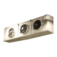
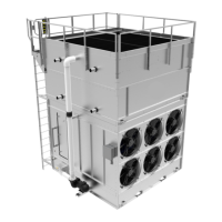
EVAPORATOR AND AIR COOLER
INSTALLATION - OPERATION - MAINTENANCE
Leave the skid on the unit and use this to lift the unit with
a forklift. Only remove the skid once the unit is mounted
to the ceiling supports. Ensure all support rods are
adequately sized to support the load. Refer to the submit-
tal drawings for the unit weight.
The equipment can be mounted using rod hangers, lag
screws, and bolts. Hang units level so that the condensate
drainage is properly maintained. Proper airow through
the unit is essential for efcient performance and main-
tenance of design storage temperatures. The minimum
spaces provided in Table 9 are recommended for unre-
stricted airow.
Table 9: Minimum spaces
Notes:
1. Do not place the cooler directly over or next to a door.
2. Do not place product directly in front of the cooler.
3. Do not place coolers in front of each other at a distance less
than their air throw, as indicated in the technical specication
sheet.
4. For electric defrost units, make sure to leave free space of at
least the length of the unit on the electric connection side to
remove the heaters in case of failure.
5. Dimensions B and C can be reduced to minimum of 6 in. on the
refrigerant connection side and for air defrost units.
6. Use deector plates for installations when dimension D is less
than the air throw indicated in the technical specication sheet.
7. If you have reduced space or special room construction, contact
your local sales ofce for advice on unit mounting.
Model type A B* C* D*
MDN 7 ft Finned
length of
the coil
Finned
length of
the coil
Air
throw of
unit
MDAN-MDAS 7 ft Finned
length of
the coil
Finned
length of
the coil
Air
throw of
unit
MDGN 7 ft Finned
length of
the coil
Finned
length of
the coil
Air
throw of
unit
MBK-MGBK 7 ft Finned
length of
the coil
Finned
length of
the coil
Air
throw of
unit
* Recommended
C
A
Airow
Airow
Airow
Airow
Airow
AF
AFAF
AF AF
AF
4 or more - unit
arrangement
AF
AF AF
Airow
Airow Airow
Airow
B B
D
Airow
Airow
Figure 2a: Unit placement and airow, one unit
Figure 2b: Unit placement and airow, two units
Figure 2c: Unit placement and airow
Figure 2d: Unit placement and airow, four units
Figure 2e: Unit placement and airow
C
2 x D