S90-555 M FRICK QUANTUM™ CONDENSER/VESSEL CONTROL PANEL
Page 18 MAINTENANCE
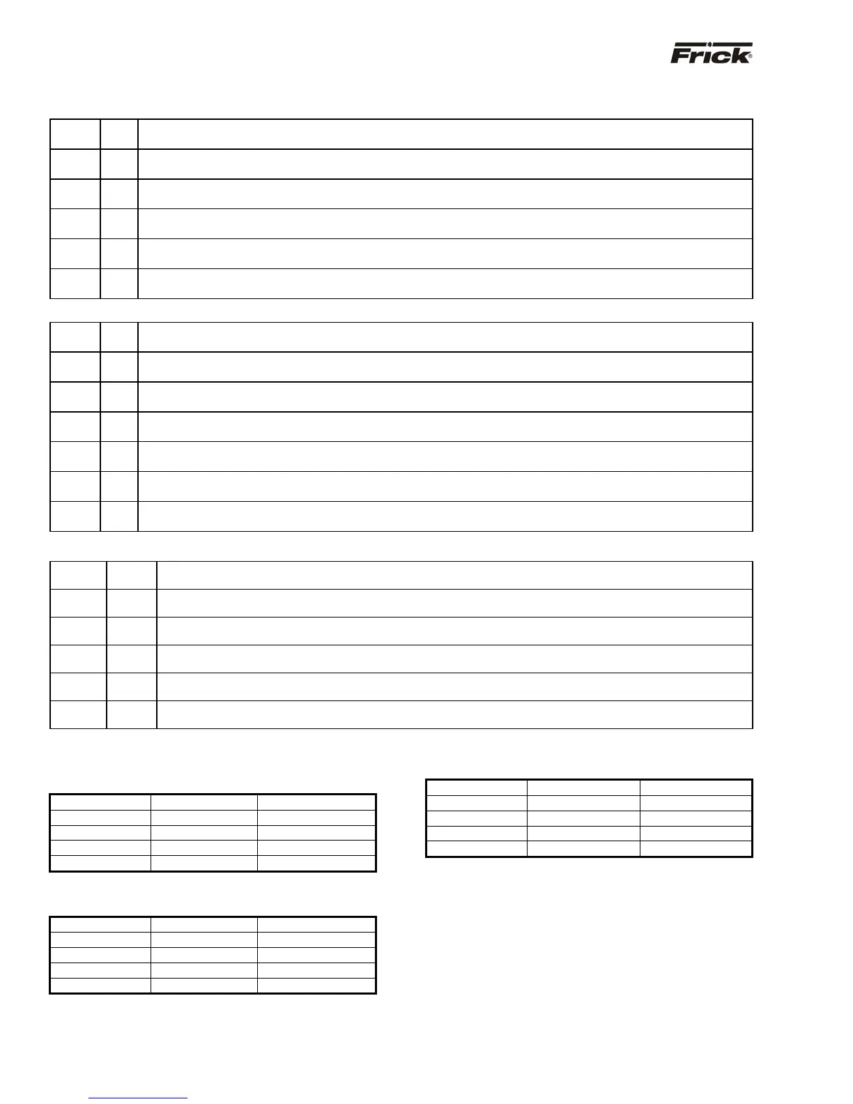
Quantum™ 3 Communications Board Jumpers
COM-1 (Jumpers located adjacent to connector TB1)
Link 1
In*
out
Pull down Rx- / Tx- (RS485) or Rx- (RS422) line to GND (0V) via a 10K resistor. (standard setting)
No pull down
Link 2
in
out*
Terminate Rx / Tx (RS485) or Rx (RS422) lines with a 120W resistor. (standard setting)
No termination (standard setting)
Link 3
in*
out
Pull up Rx+ / Tx+ (RS485) or Rx+ (RS422) line to VCC (5V) via a 10K resistor. (standard setting)
No termination.
Link 4
in*
out
Pull down Tx- (RS422) line to GND (0V) via a 10K resistor. (standard setting)
No pull down.
Link 5
in*
out
Pull up COM2 Tx+ (RS422) line to VCC (5V) via a 10K resistor. (standard setting)
No pull down.
Link 16
A*
B
RS485 (standard setting)
RS422
COM-2 (Jumpers located adjacent to connector TB2)
Link 6
In*
out
Pull down Rx- / Tx- (RS485) or Rx- (RS422) line to GND (0V) via a 10K resistor. (standard setting)
No pull down
Link 7
in
out*
Terminate Rx / Tx (RS485) or Rx (RS422) lines with a 120W resistor. (standard setting)
No termination (standard setting)
Link 8
in*
out
Pull up Rx+ / Tx+ (RS485) or Rx+ (RS422) line to VCC (5V) via a 10K resistor. (standard setting)
No termination.
Link 9
in*
out
Pull down Tx- (RS422) line to GND (0V) via a 10K resistor. (standard setting)
No pull down.
Link 10
in*
out
Pull up COM2 Tx+ (RS422) line to VCC (5V) via a 10K resistor. (standard setting)
No pull down.
Link 17
A*
B
RS485 (standard setting)
RS422
Link 19
in*
out
Select RS422/RS485 comms mode. (standard setting)
Select RS232 comms mode.
COM-3 (Jumpers located adjacent to connector TB3)
Link 11
In*
out
Pull down Rx- / Tx- (RS485) or Rx- (RS422) line to GND (0V) via a 10K resistor. (standard setting)
No
ull down
Link 12
in
out*
Terminate Rx / Tx (RS485) or Rx (RS422) lines with a 120W resistor. (standard setting)
No termination
standard settin
Link 13
in*
out
Pull up Rx+ / Tx+ (RS485) or Rx+ (RS422) line to VCC (5V) via a 10K resistor. (standard setting)
No termination.
Link 14
in*
out
Pull down Tx- (RS422) line to GND (0V) via a 10K resistor. (standard setting)
No
ull down.
Link 15
in*
out
Pull up COM2 Tx+ (RS422) line to VCC (5V) via a 10K resistor. (standard setting)
No
ull down.
Link 18
A*
B
RS485 (standard setting)
RS422
Quantum™ 3 Communications Wiring
TB1 - COM1 RS-485/422 (Used for Sequencing):
4-way screw terminal
Pin Signal (RS-422) Signal (RS-485)
4 COM1 TX+ -
3 COM1 TX- -
2 COM1 RX+ COM1 TX+ / RX+
1 COM1 RX- COM1 TX- / RX-
TB2 - COM2 RS-485/422 (Standard Communications):
4-way screw terminal
Pin Signal (RS-422) Signal (RS-485)
4 COM2 TX+ -
3 COM2 TX- -
2 COM2 RX+ COM2 TX+ / RX+
1 COM2 RX- COM2 TX- / RX-
TB3- COM3 RS-485/422: 4-way screw terminal
Pin Signal (RS-422) Signal (RS-485)
4 COM3 TX+ -
3 COM3 TX- -
2 COM3 RX+ COM3 TX+ / RX+
1 COM3 RX- COM3 TX- / RX-