S90-555 M FRICK QUANTUM™ CONDENSER/VESSEL CONTROL PANEL
Page 8 MAINTENANCE
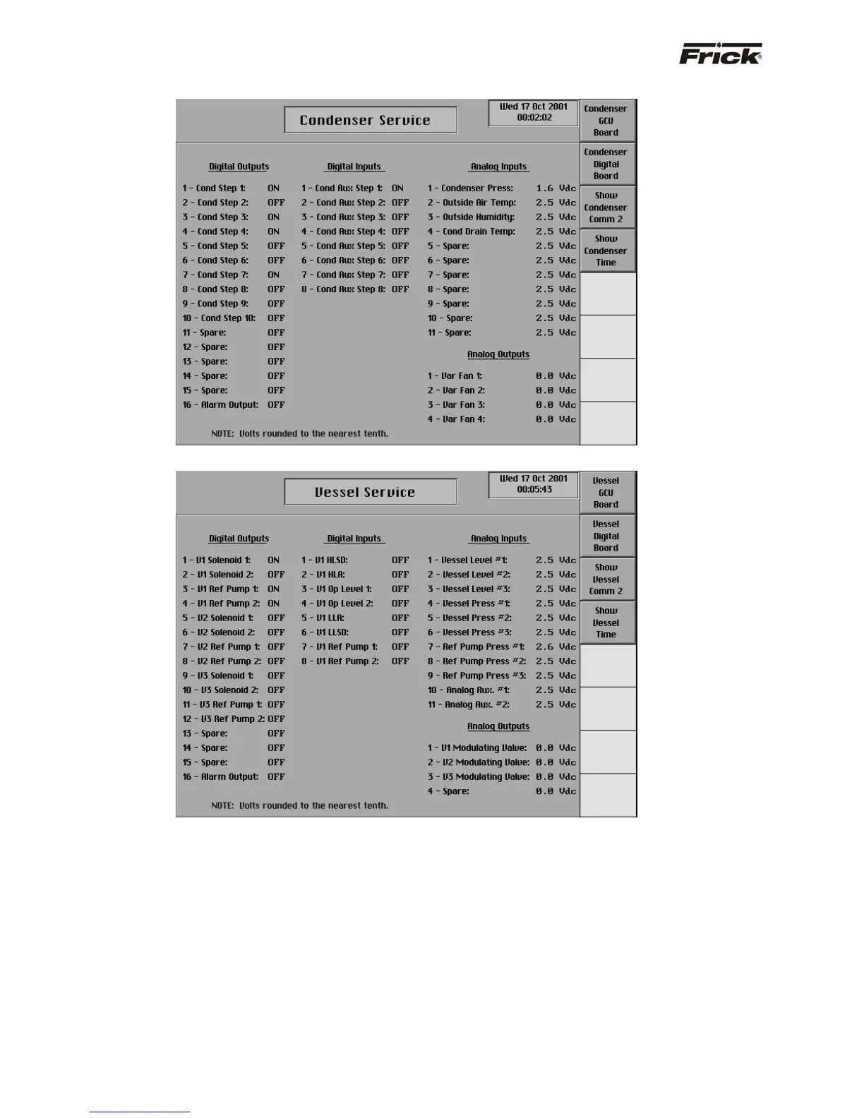
“Condenser Service” - SCREEN - GCU Board Inputs and Outputs
“Vessel Service” - SCREEN - GCU Board Inputs and Outputs
Troubleshooting Digital Inputs and Outputs
The “Service Screen” (individual service screens are
available for both Condenser and Vessel) has been
provided to view the raw data from a GCU Board. There is
a separate screen for each of the GCU Boards that are
present. Digital values are shown as ON or OFF.
Checking the Digital Inputs and Outputs
Some problems that are encountered involve
troubleshooting the digital inputs and outputs. The Digital
I/O (Input / Output) boards have three Digital I/O (DIO)
board connectors labeled J7, J9 and J10. The input and
output modules are wired to a connector plug:
Input Module
On the input module, positions 1, 3, 5, 7, 9, 11,
13, and 15 provides neutral on the DIO
connectors. Positions 2, 4, 6, 8, 10, 12, 14, and
16 are signal connections. Input modules can
only occupy the eight positions adjacent to
connector J10.
Output Module
On the output module, positions 1, 3, 5, 7, 9, 11,
13, and 15 provides signal connections. Positions
2, 4, 6, 8, 10, 12, 14, and 16 are 120 volt AC on
the DIO connectors. Output modules can only
occupy the sixteen positions adjacent to
connectors J7 and J9. Notice also, that these
sixteen positions have fuses associated with
them.