QUANTUM
™
LX CONDENSER/VESSEL CONTROL PANEL
MAINTENANCE
090.560-M (MAY 2016)
Page 14
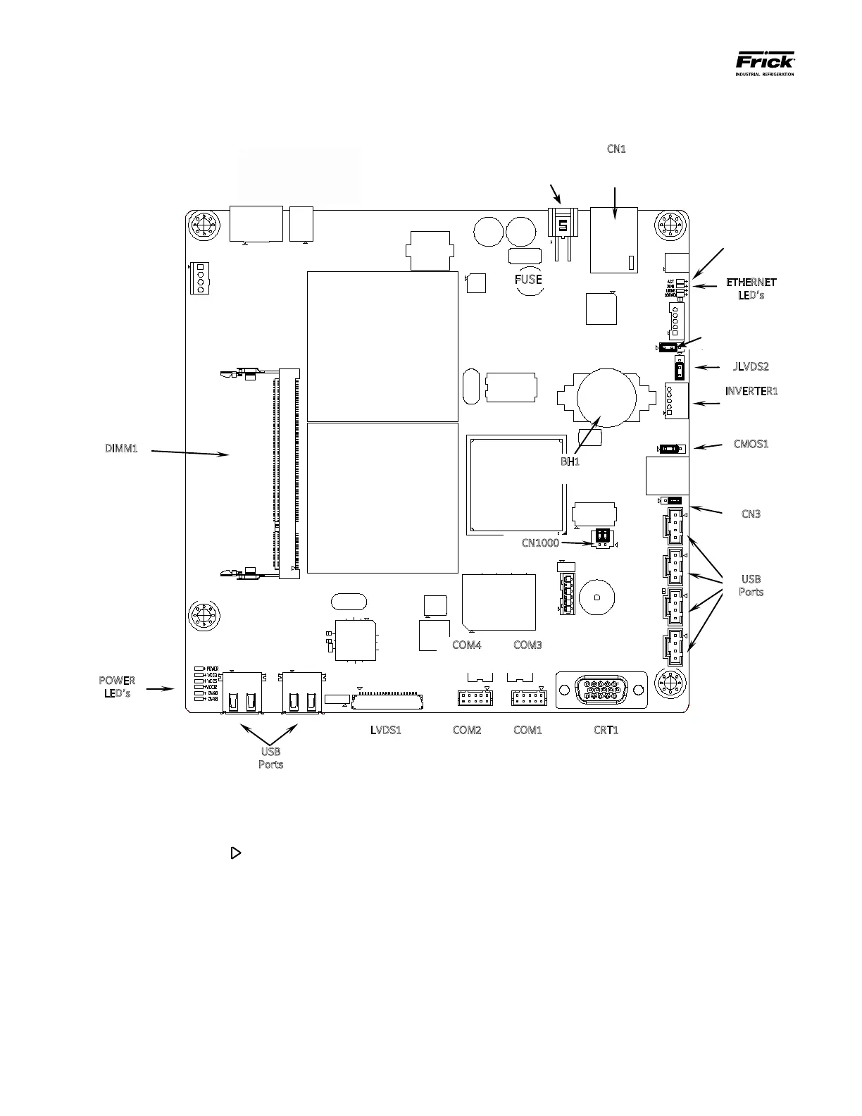
Q5 BOARD
JLVDS3
LED’s
COM4
RS-485
COM3
RS-485
Video Connector
Video Monitor
RS-232
RS-232
BH1
Battery
CN1
Ethernet
Connector
Power Connector
USB
Ports
Ports
INVERTER1
Inverter
Connector
LED’s
CN3
CN1000
under the board
here
JLVDS3
(See Note 4 below)
CN_PWR1
Power
NOTE 1: The triangle symbol ( ) denotes Pin 1 on connectors. Refer to the chart on the following page for jumper settings.
NOTE 2: Do NOT remove the CN4 jumper. Removal of this jumper will cause the processor to not power up.
NOTE 3: Although the Q5 board is the main controller, most of customer connections will be to the Interface board, as shown later.
NOTE 4: Ensure that this jumper is installed between pins 1 and 2 if a display is used that requires an inverter board. Install the jumper
between pins 2 and 3 for an LED display that does not use an inverter board. See also the jumper table on the next page for JLVDS3.