QUANTUM
™
LX CONDENSER/VESSEL CONTROL PANEL
MAINTENANCE
090.560-M (MAY 2016)
Page 44
ANALOG BOARD
ANALOG BOARD DESCRIPTION
The Analog Board is actually a small microprocessor board
and is programmed to control analog outputs, or accept
analog inputs, from external electrical devices. Each board
has the capability of 24 independent input channels. With
the Quantum™ Condenser/Vessel Control, these I/O
channels are dedicated through the software and external
wring, as to the function of each channel.
COMMUNICATIONS LED’S
The Quantum™ controller is in constant communication
with the Analog (and Digital) Board(s). You will notice on
each Analog and Digital board, that there is a pair of LED’s
that are labeled as RX and TX. These letters represent
receive (RX) and Transmit (TX). These LED’s should be
ashing at a high rate during normal operation. This
indicates that the Quantum™ LX, and the board that you
are looking at, are properly communicating with each
other.
• Refer to the JUMPER AND DIPSWITCH SETTINGS
section later in this section. This section contains
the dipswitch settings for addressing the Analog I/O
Boards. When these switches are properly set, the
Quantum™ LX is able to serially communicate with
each I/O board and provide control signals and data
exchange. If these switches are not properly set, the
result can be one of the following:
• Lost or failed communications (displayed in the
Communications Status box on the Home screen)
• The wrong analog input signals being received
• The wrong analog output signals being sent from
the board.
CONNECTIONS TO THE QUANTUM™
As stated earlier, the Quantum™ Condesnser/Vessel
control system utilizes up to two Digital, and one Analog
Board. In order to connect all of these boards together
so that the Quantum™ can control them, they must be
interconnected with a wiring harness that provides all of
the necessary D.C. voltage requirements, as well as the
communications capabilities. A diagram of this wiring
harness can be found later in this manual (see the Power
I/O Wiring Harness drawing). This harness has a 6-pin
connector at one end that plugs into the Quantum™.
Another connector plugs into the power supply. The
remaining three connectors (16 pin) will plug into each of
the Digital and Analog Boards in the system.
Upon close examination of this harness, you will notice
that each of the connectors have two rows of connections.
The wires that are inserted into the positions of one row,
are internally daisy-chained on each I/O board, to continue
the voltages and signals to the adjacent row. Therefore,
any time that a connector is unplugged from the daisy-
OVERVIEW
The Frick
®
Quantum™ LX Condenser/Vessel control panel
s are capable of reading external analog devices, such as
temperature probes and pressure sensors. It uses these
input signals for the purpose of monitoring and control.
As an example, if an external temperature sensor begins
to read a higher than expected temperature in some area,
the controller would sense this change, and provide the
necessary output control signal to remedy the situation,
or provide a warning. Unlike a digital signal, which is
typically either an on or off state, an analog signal can
assume a wide range of values, such as a temperature
probe’s reading a wide range of temperatures.
The method used for receiving (and sending) these
signals, is the analog board. The analog devices are
wired directly to the board, and the on-board software/
hardware converts the electrical signals received from
these devices into data, which is then sent on to the Q4
or Q5 control board via communications, and is monitored
by the control software.
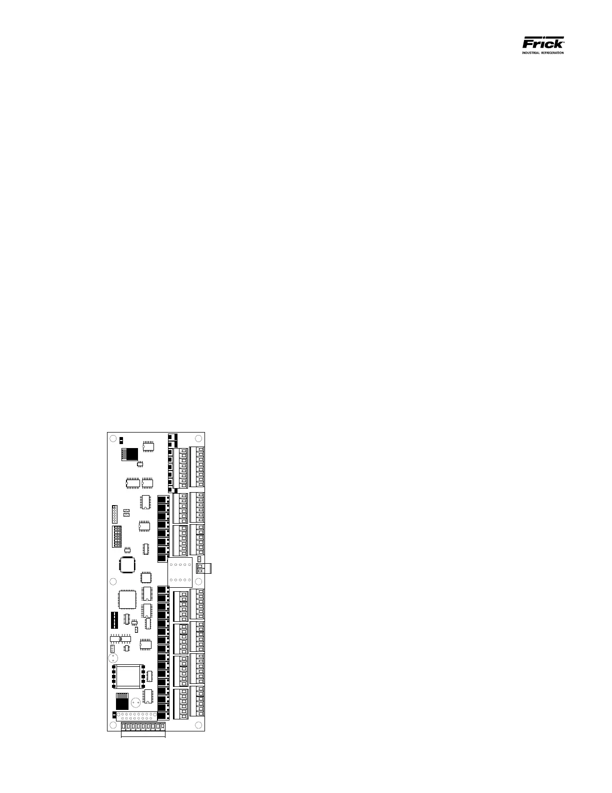
GENERAL DESCRIPTION
This board features twenty-four input channels, and
eight output channels. The board channels are congured
through software, rather than using physical jumpers. A
more detailed description of the operation of this board is
provided in the sections that follow. A drawing f this board
is shown here: