070.650-IOM (AUG 2015)
Page 20
SGC ROTARY SCREW COMPRESSOR
OPERATION
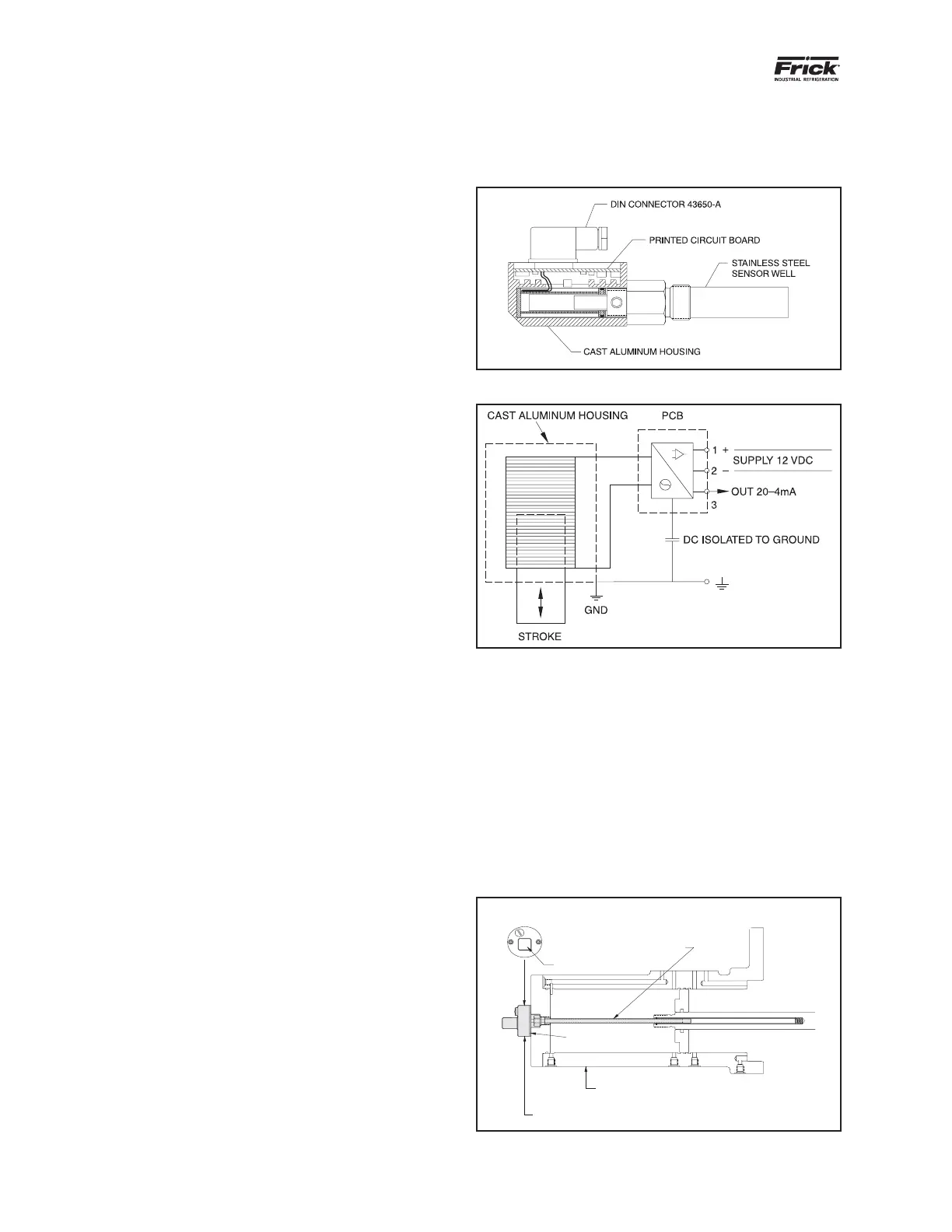
is important to achieve the most efcient compressor
operation. Connect to +/- and signal as shown in the wiring
diagram in Figure 19. Refer to Frick compressor panel
instructions 090.040-O for calibration procedure.
Figure 18. Slide Stop Transmitter
Figure 19. Wiring Diagram for Slide Stop Transmitter
CAPACITY SLIDE VALVE TRANSMITTER
The slide valve transmitter (Figure 20) measures the
position of the slide valve (SV) and sends a 4 to 20mA
signal to your control system. The controller will adjust the
position of the SV according to the motor load set point.
The correct position is important to properly load the
compressor and motor. It is important not to overload the
compressor and motor. Observe the maximum power input
and ensure design limitations are not exceeded. Connect to
+/- and signal as shown in the wiring diagram, Figure 21.
Refer to Frick compressor panel instructions for calibration
procedure 090.040-O.
ENDVIEW
DIN CONNECTOR
STAINLESS STEEL WELL
HEAT ISOLATOR
CAST ALUMINUM HOUSING
COMPRESSOR UNLOAD CYLINDER
SHADED AREA SHOWS
CAPACITY LINEAR TRANSMITTER
Figure 20. Capacity Slide Valve Transmitter
alignment is in specication (see the above “MOTOR
MOUNTING” section for mounting details).
If you are using a foot mounted motor, it is essential that
the coupling be properly aligned to ensure proper bearing
and seal performance.
1. Coupling must be selected and installed so that it
doesn’t transmit any axial load to the compressor
shaft. Assure magnetic center is set correctly on sleeve
bearing motors.
2. Set up the minimum distance between compressor
shaft and motor shaft to allow for seal removal (see
Outline drawings).
3. Coupling must be able to take up any misalignment
between motor and compressor. It is critical to the
life of the shaft seal that misalignment is kept to the
minimum possible value. Be sure to follow the coupling
manufacturer’s guidelines for checking and correcting
any misalignment. See the next section for Johnson
Controls–Frick requirements.
COUPLING ALIGNMENT REQUIREMENTS
(FOOT MOUNTED ONLY)
Coupling alignment must be performed prior to start-
up. After the compressor has been installed on the job
site, alignment must be checked again and if necessary
corrected prior to start-up. After a few hours of operation,
the alignment must be checked while the package is still
hot. Correct hot alignment is critical to ensure the life of the
shaft seal and compressor bearings.
Maximum radial runout is .004” total indicator reading.
Maximum axial runout is .004” total indicator reading.
A dial indicator or another appropriate measuring device is
to be used to determine the Total Indicator Runout.
Indicator bracket sag must be checked as all brackets have
someexibility.Thebestwaytomeasurethisistoattach
the dial indicator and bracket on a pipe at the coupling span
distance. Zero the indicator in the 12:00 position, and rotate
the pipe so the indicator is in the 6:00 position. The reading
on the indicator in the 6:00 position is the bracket sag. This
value must be included in the dial indicator readings when
afxedtothecouplingforanaccuratealignment.
DEHYDRATION / EVACUATION TEST
Evacuate the system to 1000 microns. Valve off the vacuum
pump and hold vacuum for several minutes.
Pass – Vacuum cannot rise more than 500 microns during
the hold period.
Fail – Vacuum rise is more than 500 microns during the
hold period. Identify and repair any system leaks. Repeat
vacuum test until requirements are met.
ELECTRICAL INSTALLATION
SLIDE STOP TRANSMITTER
The slide stop transmitter (Figure 18) measures the position
of the slide stop (SS) using a 20 to 4 mA signal to cover
the range of minimum to maximum Vi. The signal is sent
to your control system so that it can adjust the position of
SS according to system pressures. The correct SS position