EasyManua.ls Logo

Frick RWF Series User Manual

Frick RWF Series
56 pages
To Next Page IconTo Next Page
Page #1 background imageLoading...
Page #1 background image
Installation - Operation - Maintenance
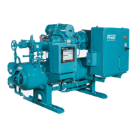
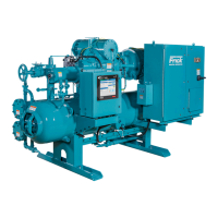
ROTARY SCREW COMPRESSOR UNITS
ALL REFRIGERANTS
MODELS
100 through 480
THIS MANUAL CONTAINS RIGGING, ASSEMBLY, START-UP, AND
MAINTENANCE INSTRUCTIONS. READ THOROUGHLY BEFORE
BEGINNING INSTALLATION. FAILURE TO FOLLOW THESE IN-
STRUCTIONS COULD RESULT IN DAMAGE OR IMPROPER OPERA-
TION OF THE UNIT.
S70-600 IOM/MAY 2001
File: SERVICE MANUAL - Section 70
Replaces: S70-600 IOM/MAR 2000
Dist: 3, 3a, 3b, 3c
RWF

Table of Contents

Questions and Answers:

Frick RWF Series Specifications

General IconGeneral
Drive TypeDirect Drive
RefrigerantR22
TypeScrew Compressor
Power Range150 to 300 HP
Cooling MethodAir or Water Cooled
Control SystemMicroprocessor-based

Summary

Preface

Compressor and Unit Identification

Compressor Data Plate

Identifies compressor model and serial number mounted on the compressor.

Unit Data Plate

Identifies unit model, serial number, and sales order number.

Design Limitations

Job Inspection

Transit Damage Claims

Foundation

Allowable Flange Loads

Table specifying maximum moments and loads for pipe connections.

Rigging and Handling

Guidelines for safely moving the compressor unit using cranes or forklifts.

Skid Removal

Procedures for removing the shipping skid from the compressor unit.

Checking Motor/Compressor Rotation

Compressor/Motor Coupling Installation

Oil Pump Coupling

Holding Charge and Storage

Compressor Unit Oil

Oil Charge

Oil Heater(s)

Oil Filter(s)

Thermosyphon Oil Cooling

Oil Temperature Control

Guidance on oil temperature control relative to condensing temperature.

Installation - Thermosyphon Oil Cooling

Liquid Injection Oil Cooling (Optional)

Liquid Line Sizes/Receiver Volume

Water-Cooled Oil Cooling (Optional)

Oil Cooler Data Table

Table detailing oil cooler specifications and connection sizes.

Economizer - High Stage (Optional)

Shell and Coil Economizer System

Diagram and description of a shell and coil economizer system.

Flash Economizer System

Diagram and description of a flash economizer system.

Direct Expansion Economizer System

Diagram and description of a direct expansion economizer system.

Multiple Compressor Economizer System

Diagram illustrating economizer system for multiple compressors.

Economizer Load Balancing

Electrical

Motor Starter Package

Components and considerations for motor starter packages.

Current Transformer (CT) Ratios

Minimum Burden Ratings

Control Power Regulator

Battery Backup

Operation and Start-up Instructions

SGC Compressor

Compressor Lubrication System

No Pump Oil System

Description of the self-lubricating system without a dedicated oil pump.

Cold-Start System

Demand Pump Oil System

Compressor Oil Separation System

Oil Separation Systems

Diagram of oil separation systems for horizontal models.

Compressor Hydraulic System

Single-Acting Mode - High Stage

Operation of the hydraulic system for high-stage compressors.

Double-Acting Mode - Booster

Operation of the hydraulic system for booster compressors.

Volumizer® Volume Ratio Control

Compressor Oil Cooling Systems

Single-Port Liquid Injection

Booster or Swing Duty Application

Dual-Port Liquid Injection

Liquid Injection Adjustment Procedure

Steps for adjusting the liquid injection system for optimal oil temperature.

Suction Check Valve Bypass

Low Ambient Operation

Initial Start-up

Initial Start-up Procedure

Detailed steps for performing the initial start-up.

Normal Start-up Procedure

Steps for a normal start-up after initial setup.

Restarting Compressor Unit After Control Power Interruption

Procedure for restarting after a power failure.

General Information

Normal Maintenance Operations

General Maintenance

Compressor Shutdown and Start-up

General Instructions for Replacing Compressor Unit Components

Oil Filter (OF-1) Main Single/Dual

Strainer - Demand Oil Pump

Strainer - Liquid Injection

Coalescer Filter Element(s)

Changing Oil

Demand Pump Disassembly

Thrust-Bearing Assembly (GG, HJ, HL)

Illustration and steps for thrust-bearing assembly.

Thrust-Bearing Assembly (AS, AK, AL)

Illustration and steps for thrust-bearing assembly.

Demand Pump Assembly

Rotor Hub

Illustration of rotor hub components.

Spring

Illustration of spring and mechanical seal.

Installation of Carbon Graphite Bushings

Troubleshooting the Demand Pump

Vacuum Gauge - Suction Port

Interpretation of vacuum gauge readings on the suction port.

Pressure Gauge - Discharge Port

Troubleshooting Pump Issues

Preventative Maintenance

Recommended Maintenance Program

Vibration Analysis

Motor Bearings

Oil Quality and Analysis

Lubrication Schedule / Instructions

Operating Log

Maintenance Schedule

Troubleshooting Guide

Abnormal Operation Analysis and Correction

Servicing the Cold-Start Valve

Warning regarding servicing the cold-start valve.

Pressure Transducers - Testing

Procedure for testing pressure transducers.

Pressure Transducer Conversion Data

Pressure Transducers - Replacement

SV Position Potentiometer Replacement and Adjustment

Capacity Linear Transmitter Replacement - Slide Valve

Volumizer® Transmitter Replacement - Slide Stop

Oil Level Transmitter Replacement

Temperature Sensor Replacement

Troubleshooting the RWF Compressor

Troubleshooting the Oil Separation System

Troubleshooting the Hydraulic System

Troubleshooting the Liquid Injection Oil Cooling System

Troubleshooting the Demand Pump System

Thermal Expansion Valves

R-717 TX Valve Sizes

Table of R-717 TX valve sizes and port connections.

R-22 TX Valve Sizes

Table of R-22 TX valve sizes and port connections.

Jordan Temperature Regulator Valve

Adjustment

How to adjust spring tension for oil temperature control.

Action

How to set the valve for direct or reverse acting operation.

Stroke Adjustment

Procedure for making a stroke adjustment on the valve.

Motor Replacement

Bare Compressor Replacement

Shutdown Due to Improper Oil Pressure

Grease Compatibility

P & I Diagram

P & I Diagram - Optional Dual Oil Filters, Demand Oil Pump, Thermal Control Valve

Legend

P & I Diagram, Liquid Injection – Single Port

P & I Diagram, Liquid Injection – Dual Port

P & I Diagram, Liquid Injection – Booster

Wiring Harness - External Transducers for Board #1

Wiring Harness - External AC to Heaters and Valves

Wiring Harness - Internal Analog Board #1

Wiring Harness - AC Conduit - Quantum to DBS Panel

Proper Installation of Electronic Equipment in an Industrial Environment

Wire Sizing

Recommendations for sizing supply wires to minimize voltage dips.

Voltage Source

Importance of selecting a clean, separate voltage source for controls.

Grounding

Wiring Practices

Proper Installation of Electronic Equipment

Screw Compressor Operating Log Sheet

RWF Compressor Prestart Checklist

Mechanical Checks

List of mechanical checks to perform before start-up.

Electrical Checks

List of electrical checks to perform before start-up.

Start-up Report

Adjustable Safety Setpoints

Drive Train Alignment

Initial Cold Alignment

Steps for initial cold alignment of the drive train.

Initial Hot Alignment

Steps for initial hot alignment of the drive train.

Final Hot Alignment

Steps for final hot alignment of the drive train.

Operating Log Sheet

Vibration Data Sheet

Recommended Spare Parts - Current Design

Related product manuals