RWF ROTARY SCREW COMPRESSOR UNITS
INSTALLATION
S70-600 IOM
Page 7
B
C
A
OPT. OIL TEMP
CONTROL VALVE
HOT
REFRIGERANT
OUT
REFRIGERANT IN
COOL
COOL
OIL OUT
HOT OIL IN
LIQUID
LEVEL
STATIC HEAD
TO OVERCOME
CONDENSER
PRESSURE DROP
6 Ft.
Min.
SYSTEM
CONDENSER
SAFETY
VALVE
VAPOR
THERMOSYPHON
RECEIVER
LIQUID OVERFLOW
DRAIN TO RECEIVER
TO SYSTEM
EVAPORATOR
SYSTEM
RECEIVER
1
3
4
(Mounted below Thermosyphon
receiver level)
2
PLATE COOLER
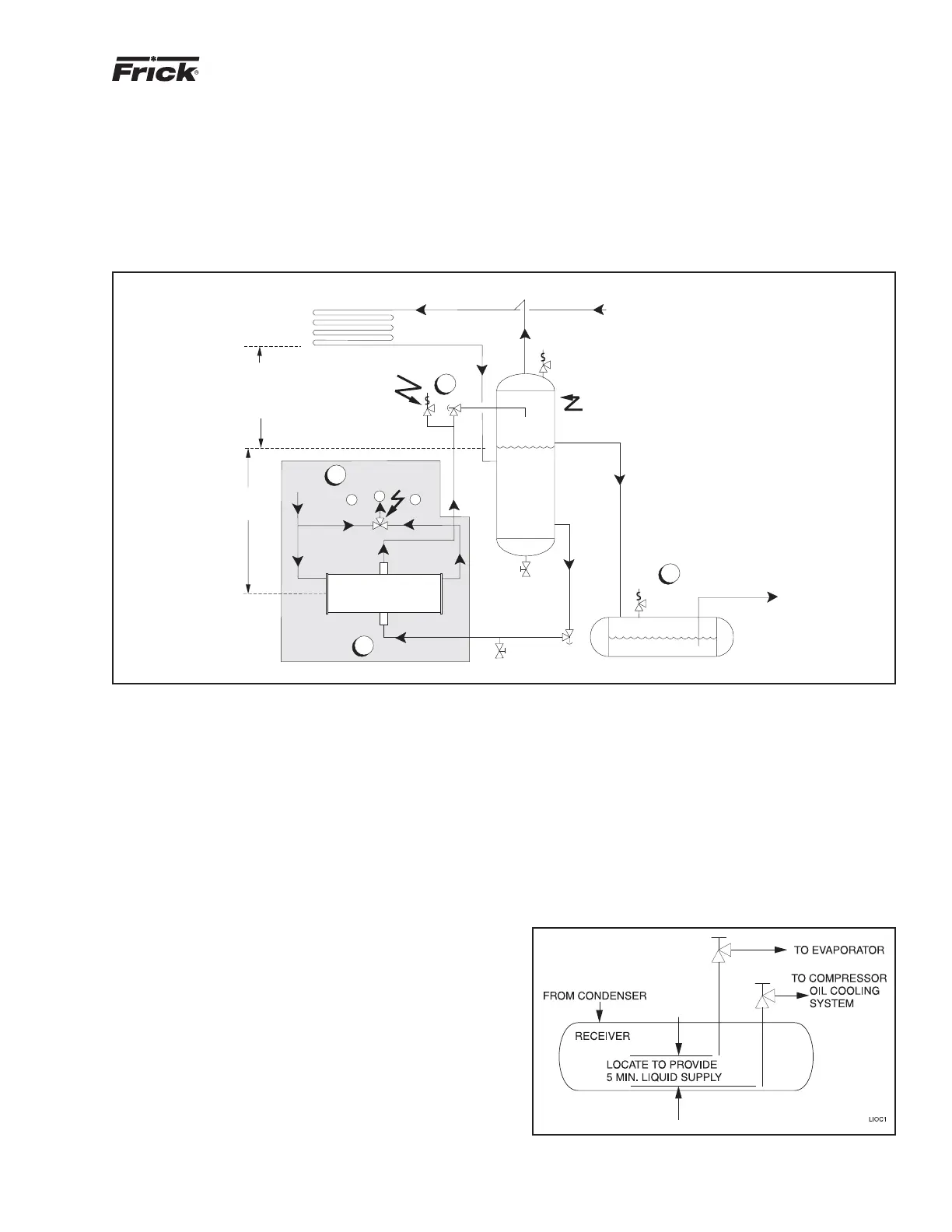
TSOC
Figure 3
1. The thermosyphon oil cooler is supplied with the oil side piped to the compressor unit and stub ends supplied on the refrigerant side.
2. A three-way oil temperature control valve is required where condensing temperature is expected to go below 65°F.
3. A refrigerant-side safety valve is required in this location only when refrigerant isolation valves are installed between the cooler and
thermosyphon receiver. If no valves are used between the cooler and TSOC receiver, the safety valve on the TSOC receiver must be sized
to handle the volume of both vessels. Then, the safety valve on the cooler vent (liquid refrigerant side) can be eliminated.
4. The system receiver must be below the thermosyphon receiver in this arrangement.
LIQUID INJECTION OIL COOLING (Optional)
The liquid injection system provided on the unit is self-con-
tained but requires the connection of the liquid line sized as
shown in the table and careful insertion of the expansion valve
bulb into the thermowell provided in the separator. High pres-
sure gas is connected through the regulator to the external
port on the liquid injection valve to control oil temperature.
NOTE: For booster applications the high pressure gas
connection must be taken from a high side source (high
stage compressor discharge). This should be a 3/8" line
connected into the solenoid valve provided. This gas is
required by the expansion valve external port to control
oil temperature.
It is IMPERATIVE that an uninterrupted supply of high pres-
sure liquid refrigerant be provided to the injection system at
all times. Two items of EXTREME IMPORTANCE are the
design of the receiver/liquid injection supply and the size of
the liquid line.
It is recommended that the receiver be oversized sufficient-
ly to retain a 5-minute supply of refrigerant for oil cooling.
INSTALLATION - The plate and shell type thermosyphon
oil cooler with oil-side piping and a thermostatically con-
trolled mixing valve (if ordered) are factory mounted and
piped. The customer must supply and install all piping and
equipment located outside of the shaded area on the piping
diagram with consideration given to the following:
1. The refrigerant source, thermosyphon or system receiv-
er, should be in close proximity to the unit to minimize pip-
ing pressure drop.
The evaporator supply must be secondary to this consider-
ation. Two methods of accomplishing this are shown.
The dual dip tube method (Figure 4) uses two dip tubes in
the receiver. The liquid injection tube is below the evaporator
tube to ensure continued oil cooling when the receiver level
is low.
Figure 4
2. The liquid level in the refrigerant source must be 6 to 8
feet minimum above the center of the oil cooler.
3. A safety valve should be installed if refrigerant isolation
valves are used for the oil cooler.
The component and piping arrangement shown in Figure 3 is
intended only to illustrate the operating principles of thermo-
syphon oil cooling. Other component layouts may be better
suited to a specific installation. Refer to publication E70-900E
for additional information on Thermosyphon Oil Cooling.