RWF ROTARY SCREW COMPRESSOR UNITS
INSTALLATION
S70-600 IOM
Page 6
OIL CHARGE
The normal charging level is
midway in the top sight glass lo-
cated midway along the oil sepa-
rator shell. Normal operating level
is midway between the top sight
glass and bottom sight glass. The
table gives the approximate oil
charge quantity.
* Includes total in oil separator and
piping. Add 5 gal. for oil cooler.
Add oil by attaching the end of a suitable pressure type hose
to the oil charging valve, located on the top of the oil sepa-
rator between the compressor and motor. Using a pressure-
type pump and the recommended Frick oil, open the charg-
ing valve and pump oil into the separator. NOTE: Fill slowly
because oil will fill up in the separator faster than it
shows in the sight glass.
Oil distillers and similar equipment which act to trap oil must
be filled prior to unit operation to normal design outlet lev-
els. The same pump used to charge the unit may be used
for filling these auxiliary oil reservoirs.
NOTE: The sight glass located in the coalescing end of
the separator near the discharge connection should re-
main empty.
OIL HEATER(S)
Standard units are equipped with two or three 500 watt oil
heaters, providing sufficient heat to maintain the oil tem-
perature for most indoor applications during shutdown cycles
to permit safe start-up. Should additional heating capacity
be required because of low ambient temperature, contact
Frick. The heaters are energized only when the unit is not in
operation.
DO NOT ENERGIZE THE HEATERS
when there is no oil in the unit, the
heaters will burn out. The oil heat-
ers will be energized whenever 120 volt control power is
applied to the unit and the compressor is not running,
unless the 16 amp circuit breaker in the micro enclo-
sure is turned off.
OIL FILTER(S)
Use of filter elements other than
Frick must be approved in writing
by Frick engineering or warranty
claim may be denied.
The oil filter(s) and coalescer filter element(s) shipped with
the unit are best suited to ensure proper filtration and op-
eration of the system.
THERMOSYPHON OIL COOLING
Thermosyphon oil cooling is an economical, effective
method for cooling oil on screw compressor units. Ther-
mosyphon cooling utilizes liquid refrigerant at condenser
pressure and temperature that is partially vaporized at the
condenser temperature in a plate and shell vessel, cooling
the oil to within 15°F of that temperature. The vapor, at con-
densing pressure, is vented to the condenser inlet and
reliquified. This method is the most cost effective of all cur-
rently applied cooling systems since no compressor ca-
pacity is lost or compressor power penalties incurred. The
vapor from the cooler need only be condensed, not com-
pressed. Refrigerant flow to the cooler is automatic, driven
by the thermosyphon principle and cooling flow increases
as the oil inlet temperature rises.
EQUIPMENT - The basic equipment required for a ther-
mosyphon system consists of:
1. A source of liquid refrigerant at condensing pressure and
temperature, located in close proximity to the unit to mini-
mize piping pressure drop. The liquid level in the refrigerant
source must be 6 to 8 feet minimum above the center of the
oil cooler.
2. A plate and shell oil cooler with:
Plate Side: Oil 400 lb design
Shell Side: Refrigerant 400 lb design
Due to the many variations in refrigeration system design
and physical layout, several systems for assuring the above
criteria are possible.
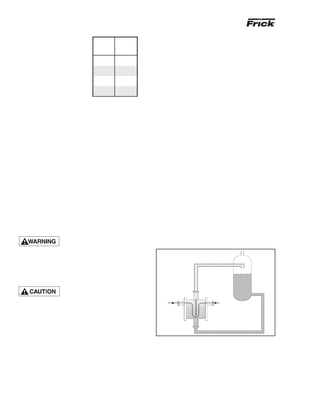
SYSTEM OPERATION - Liquid refrigerant fills the cooler
shell side up to the Thermosyphon receiver liquid level.
Hot oil (above the liquid temperature) flowing through the
cooler will cause some of the refrigerant to boil and vapor-
ize. The vapor rises in the return line. The density of the
refrigerant liquid/vapor mixture in the return line is consider-
ably less than the density of the liquid in the supply line.
This imbalance provides a differential pressure that sustains
a flow condition to the oil cooler. This relationship involves:
1. Liquid height above the cooler.
2. Oil heat of rejection.
3. Cooler size and piping pressure drops.
Current thermosyphon systems are using two-pass oil cool-
ers and flow rates based on 3:1 overfeed.
The liquid/vapor returned from the cooler is separated in the re-
ceiver. The vapor is vented to the condenser inlet and need only be
reliquified since it is still at condenser pressure. See Figure 2.
100 50
134 50
177 95
222 95
270 140
316 140
399 140
480 140
BASIC*
CHARGE
(gal.)
RWF
MODEL
NO.
Figure 2
OIL TEMPERATURE CONTROL - Oil temperature will gen-
erally run about 15 - 35°F above condensing temperature.
In many cases, an oil temperature control is not required if
condensing temperature is above 65°F as oil temperature
can be allowed to float with condenser temperature.
Condensing Temperature: 65°F - 105°F
Oil Temperature: 80°F - 140°F
HOT OIL IN
FROM
SEPARATOR
120-140 F
OIL OUT
O
TO SYSTEM CONDENSER
95 F
2.5#/FT
O
3
95 F
36#/FT
O
3
TS RECEIVER