RWF ROTARY SCREW COMPRESSOR UNITS
INSTALLATION
S70-600 IOM
Page 5
CHECKING MOTOR/COMPRESSOR ROTATION
Make sure coupling hubs are tight-
ened to the shaft before rotating the
motor to prevent them from flying
off and possibly causing serious injury or death.
Injury may occur if loose clothing,
etc, becomes entangled on the spin-
ning motor shaft.
COMPRESSOR ROTATION IS CLOCKWISE WHEN FAC-
ING THE END OF THE COM-
PRESSOR SHAFT. Under NO
conditions should the motor ro-
tation be checked with the cou-
pling center installed as dam-
age to the compressor may re-
sult. Bump the motor to check
for correct compressor rotation.
After verification, install disk
drive spacer, as applicable.
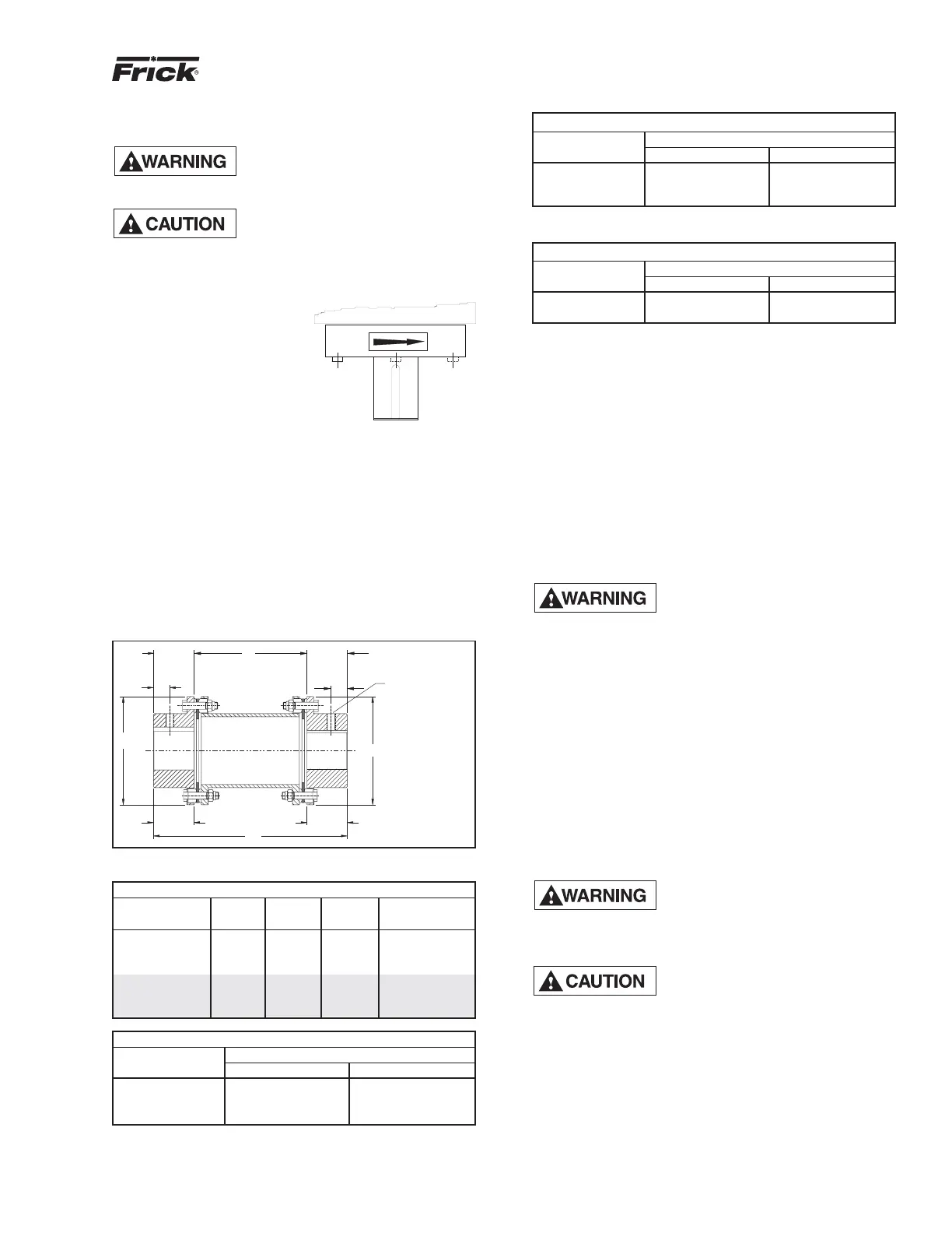
COMPRESSOR/MOTOR COUPLING
INSTALLATION
The RWF unit has compressor to motor alignment through
the use of a machined cast iron tunnel. This tunnel is factory
set through machining tolerances ensuring motor compres-
sor alignment. No alignment is required in the field. For
replacement motors, the shaft alignment should be checked
and tolerances verified with the Frick service department.
See Figure 1.
1/2-20UNF
SET SCREW
LOCATE ONE OVER
KEYWAY AND ONE AT
90 FROM KEYWAY
O
12
2 1/2
MIN
2 1/2
MIN
HUB LENGTH HUB LENGTH
7
BETWEEN
SHAFTS
2.50
MIN
2.75
MAX
SHAFT
ENGAGEMENT
2.50
MIN
2.75
MAX
SHAFT
ENGAGEMENT
6.62 ø
6.62 ø
1
1
Figure 1
TORSIONAL DATA
COUPLING MOTOR WEIGHT INERTIA TORSIONAL
PART NO. HUB (lb) lb x in.
2
in. x lb/RADIAN
720C0044H01 2.377 32.4 152 2.89 x 10
6
720C0044H02 2.127 33.1 153 2.89 x 10
6
720C0044H03 1.877 33.8 154 2.89 x 10
6
720C0045H01 2.377 52.6 334 4.58 x 10
6
720C0045H02 2.127 53.5 335 4.33 x 10
6
720C0045H03 2.877 50.7 330 5.06 x 10
6
OPERATING DATA - 60 Hz
SPECIFICATION COUPLING PART NO.
(Maximum) 720C0044H0_ 720C0045H0_
Power (hp) 424 740
Speed (rpm) 3,600 3,600
Torque* (in.-lb) 11,130 19,425
*Includes 1.5 service factor.
ALTERNATE OPERATING DATA - 50 Hz
COUPLING PART NO.
SPECIFICATION 720C0044H0_ 720C0045H0_
Power (hp) 424 740
Speed (rpm) 3,000 3,000
Torque* (in.-lb) 13,356 23,310
*Includes 1.5 service factor.
COUPLING TORQUE RATINGS
COUPLING PART NO.
TORQUE 720C0044H0_ 720C0045H0_
Max continuous 17,500 in.-lb 24,300 in.-lb
Peak overload 35,000 in.-lb 48,600 in.-lb
OIL PUMP COUPLING
Compressor units with direct motor/pump coupled pumps
need no pump/motor coupling alignment since this is main-
tained by the close-coupled arrangement.
HOLDING CHARGE AND STORAGE
Each RWF compressor unit is pressure and leak tested at
the Frick factory and then thoroughly evacuated and charged
with dry nitrogen to ensure the integrity of the unit during
shipping and short term storage prior to installation.
NOTE: Care must be taken when entering the unit to
ensure that the nitrogen charge is safely released.
Holding-charge shipping gauges
on separator and external oil cooler
are rated for 30 PSIG and are for
checking the shipping charge only. They must be re-
moved before pressure testing the system and before
charging the system with refrigerant. Failure to remove
these gauges may result in catastrophic failure of the
gauge and uncontrolled release of refrigerant resulting
in serious injury or death.
All units must be kept in a clean, dry location to prevent
corrosion damage. Reasonable consideration must be given
to proper care for the solid state components of the micro-
processor.
Units which will be stored for more than two months must
have the nitrogen charge checked periodically.
COMPRESSOR UNIT OIL
DO NOT MIX OILS of different
brands, manufacturers, or types.
Mixing of oils may cause excessive
oil foaming, nuisance oil level cutouts, oil pressure loss,
gas or oil leakage and catastrophic compressor failure.
Use of oils other than Frick Oil must
be approved in writing by Frick en-
gineering or warranty claim may be
denied.
The oil charge shipped with the unit is the best suited lubri-
cant for the conditions specified at the time of purchase. If
there is any doubt due to the refrigerant, operating pres-
sures, or temperatures; refer to Frick Pub. E160-802 SPC
for guidance.
MPRE
R