RWF ROTARY SCREW COMPRESSOR UNITS
OPERATION
S70-600 IOM
Page 16
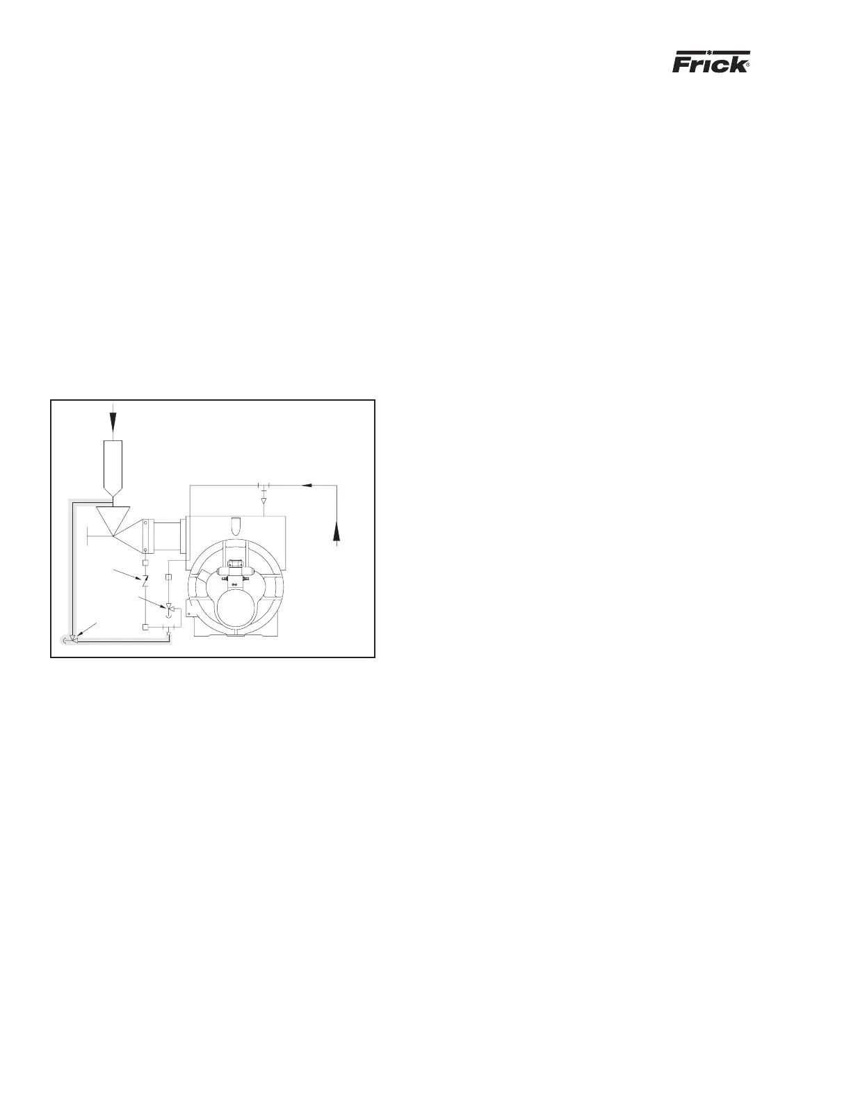
SUCTION CHECK VALVE BYPASS
The RWF unit is equipped with a low-pressure-drop suc-
tion check valve bolted directly to the compressor housing.
Units that have an 8" stop valve or larger will be piped as
shown in the shaded area of the illustration below. During
normal operation, valve HV-1 is closed. This is a pump-out
connection to allow refrigerant removal to the system suc-
tion prior to evacuation for servicing. Valve HV-2 must be
open in most systems at all times. It should normally be
cracked open to allow the oil separator to slowly bleed
down to system suction pressure when the unit is stopped
(having this valve cracked open allows the compressor drive
motor to have an easier start, and the discharge check valve
will seat more tightly). If the drive coupling backspins, the
valve should be adjusted down until the backspin stops. If
the separator oil level foams excessively on shutdown, HV-
2 should be closed slightly. If the separator takes more than
20 – 30 minutes to equalize to suction pressure after shut-
down, HV-2 can be opened slightly. See Figure 17.
SE-1
SC-5
FROM
SEPARATOR
COLD-START
VALVE
SUCTION GAS
TO THE COMPR
HV-1
HV-2
CK-1
Figure 17
Check valve CK-1 is installed on all RWF packages with
suction pressure below atmospheric or when installed with
economizer option utilized on multiple compressor plants.
On high-stage systems, check valve CK-1 should be installed
with a 40 psi spring to avoid the possibility of back-feeding
to a shut-down compressor from a common economizer ves-
sel.
On booster systems, check valve CK-1 should be installed
with a 15 psi spring to avoid the possibility of air ingress into
the system, if the system suction pressure is below atmo-
spheric.
HV-2 should be closed, on systems that utilize autocycle to
restart the compressor, based on increase in system suc-
tion pressure during shutdown, if slowly bleeding the oil sepa-
rator gas to suction will raise the suction pressure enough
to cause short cycling of the compressor.
Also, it is important to close HV-2, if the oil pump is to be run
for long periods of time with the compressor stopped, to
avoid oil being pumped up the suction line.
LOW AMBIENT OPERATION
It is recommended that oil separators be insulated as a
minimum requirement to preserve the heat generated by
the oil heaters. It is important that the coalescer end of the
separator be insulated to prevent refrigerant condensation.
On systems located outdoors or in unheated buildings where
the ambient temperature could drop below +40°F, insulating
and/or heat tracing of the compressor lube oil systems is
highly recommended.
When low ambient temperatures (below +20°F) are a possi-
bility, it is recommended that lube oil lines, oil filters, oil
pumps, and oil coolers be heat traced and insulated.
Freeze-up protection must also be provided for all water-
cooled equipment