RWF ROTARY SCREW COMPRESSOR UNITS
INSTALLATION
S70-600 IOM
Page 8
WATER-COOLED OIL COOLING (OPTIONAL)
The plate and shell type water-cooled oil cooler is mounted
on the unit complete with all oil piping. The customer must
supply adequate water connections and install the two-way
water regulating valve if ordered in lieu of a three-way oil
temperature valve. It is recommended (local codes permit-
ting) that the water regulator be installed on the water outlet
connection. Insert the water regulator valve bulb and well in
the chamber provided on the oil outlet connection. Deter-
mine the size of the water-cooled oil cooler supplied with
the unit, then refer to table for the water connection size.
The water supply must be sufficient to meet the required
flow.
Frick recommends a closed-loop system for the waterside
of the oil cooler. Careful attention to water treatment is es-
sential to ensure adequate life of the cooler if cooling tower
water is used. It is imperative that the condition of cool-
ing water and closed-loop fluids be analyzed regularly
and as necessary and maintained at a pH of 7.4, but not
less than 6.0 for proper heat exchanger life. After initial
start-up of the compressor package, the strainer at the inlet
of the oil cooler should be cleaned several times in the first
24 hours of operation.
In some applications, the plate and shell oil cooler may be
subjected to severe water conditions, including high tem-
perature and/or hard water conditions. This causes acceler-
ated scaling rates which will penalize the performance of
the heat exchanger. A chemical cleaning process will ex-
tend the life of the Plate and Shell heat exchanger. It is im-
portant to establish regular cleaning schedules.
Cleaning: A 3% solution of Phosphoric or Oxalic Acid is
recommended. Other cleaning solutions can be obtained
from your local distributor, but they must be suitable for stain-
less steel. The oil cooler may be cleaned in place by back
flushing with recommended solution for approximately 30
minutes. After back flushing, rinse the heat exchanger with
fresh water to remove any remaining cleaning solution.
NOTE: The water-regulating valve shipped with the unit
will be sized to the specific flow for the unit.
OIL COOLER DATA TABLE
RWF TYPICAL CONNECTION
MODEL COOLER INLET OUTLET
100/134 High Stage 116 Plates 3
"
3
"
100 - 270 Booster 66 Plates 2
"
2
"
177/222 High Stage 190 Plates 3
"
3
"
270 High Stage 288 Plates 3
"
4
"
316/399 Booster 56 Plates 3
"
3
"
316/399 High Stage 136 Plates 4
"
5
"
480 Booster 72 Plates 3
"
3
"
480 High Stage 188 Plates 4
"
5
"
*Based on 100 foot liquid line. For longer runs, increase
line size accordingly.
LIQUID LINE SIZES/RECEIVER VOLUME
Liquid line sizes and the additional receiver volume (quanti-
ty of refrigerant required for 5 minutes of liquid injection oil
cooling) are given in the following table:
LIQUID LINE SIZE and RECEIVER VOLUME
LINE SIZE* POUND LIQUID
RWF SCH 80 OD PER VOLUME
MODEL PIPE TUBING 5 MIN. CU FT
R-717 HIGH STAGE*
100-134 3/4 – 80 2.0
177-270 1 – 140 4.0
316-480 1-1/4 – 250 7.0
R-717 BOOSTER*
100-134 1/2 – 20 0.5
177-270 3/4 – 30 1.0
316-480 1 – 40 1.5
R-22 HIGH STAGE*
100-134 1-1/4 1-1/8 290 4.0
177-270 1-1/2 1-3/8 570 8.0
316-480 2 2-1/2 1,050 14.0
R-22 BOOSTER*
100-134 3/4 7/8 44 0.6
177-270 3/4 7/8 59 0.8
316-480 3/4 7/8 92 1.2
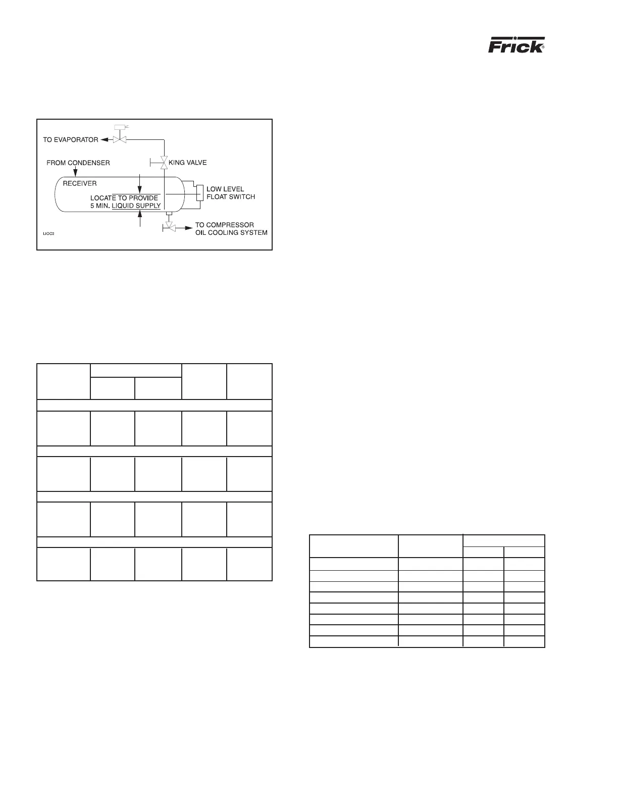
The level-control method (Figure 5) utilizes a float level
control on the receiver to close a solenoid valve feeding the
evaporator when the liquid falls below that amount neces-
sary for 5 minutes of liquid injection oil cooling.
Figure 5